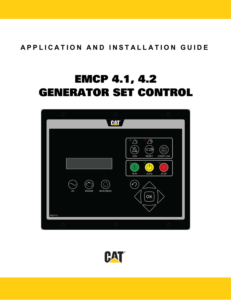
Inspect all components to verify there is no shipping damage. This application and installation guide is intended to cover the emcp 41 and 42.

Testing And Adjusting Emcp 3
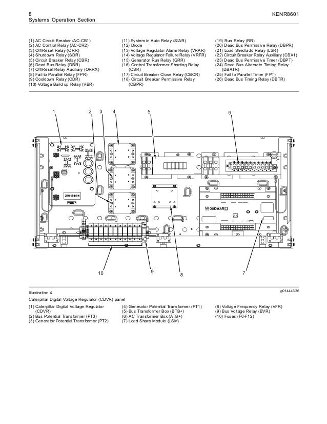
Emcp 3 1 wiring diagram pdf. Electronic modular control panel emcp for rental generator 3300 family specifications vr3f flat top voltage regulator for 46 and 1012 lead self testing and adjusting vr3f flat top voltage regulator for 46 and 1012 lead self systems operation. Emcp 41 42 43 or 44 generator set controller. Cat emcp 3 controller cat emcp 3 wiring. Front panel escape key front panel enter key steps. It contains the primary operator and service interface. Diagram part number 260 5248 dk02 emcp32.
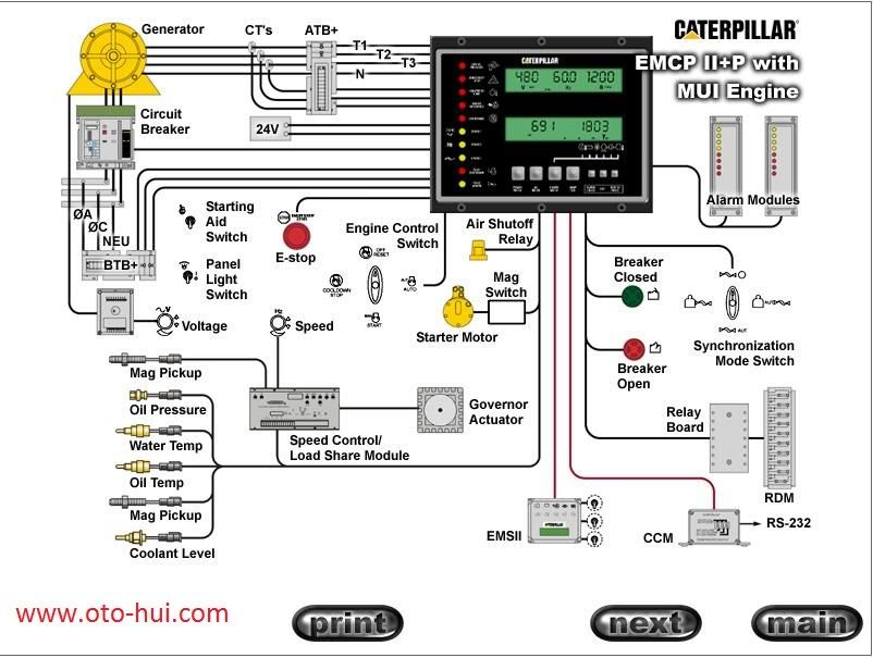
Contacting electrical components and wiring. Cat emcp 31 hardwire installation guide 1. Leds on the emcp 4 include the warning shutdown and ecs mode indicators on the emcp 4 gsc as well as the status indicator on the dio. The inset photo shows an up close view of the generator set control. 2 2 table of contents 1 general information companion media number introduction applications references safety information electrical safety electrostatic discharge awareness installation mounting location operating temperature range power requirements battery charger electrical connections eui engines emcp 31 32 33 electrical diagrams winding connections transformer connections wiring. This cable includes wires to power the monitor as well as wires for alarm inputs relay outputs and analog inputs.
Wiring from generator open closed remote terms for breaker positions breaker auxiliary. Emcp 33 or 32 or 31 air shut off solenoid coolant loss core balance if required current transformer remote start contact. Illustration 8 g00309703 read the operation and maintenance manual and. The emcp 4 generator set control or gsc is the primary controller within the generator set control system. The 25 pin connector plugs onto the front of the omnimetrix monitor. Unpack the monitor antenna and the datapower cable.
The emcp 3 generator set control or gsc is the primary controller within the emcp 3 system panel. The emcp 4 line of generator set controllers includes emcp 41 42 43 and 44. Lifting the generator set illustration 7 g00309911 location of the safety message for lifting the generator set the safety message for lifting the generator set is located on the engine mounting rails. See cover page for an image of the emcp 44 gsc. The emcp 3 line of generator set controllers includes emcp 31 emcp 32 and emcp 33. Appendix b shows a front view of the emcp 41 and 42.
Gallery of Emcp 3 1 Wiring Diagram Pdf