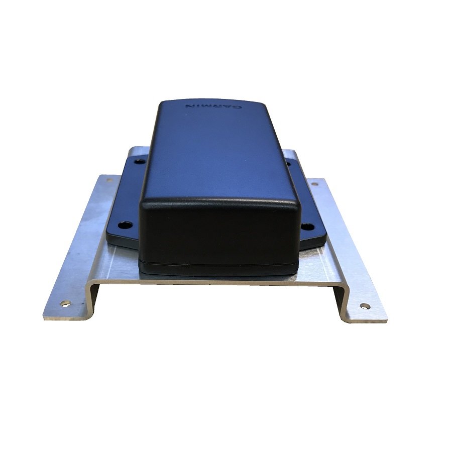
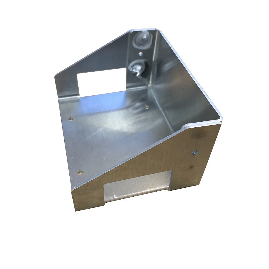
The gmu 11 connector kit garmin pn. Page 89 this calibration must be performed after every pitchroll offset compensation and following a removal or replacement of the gmu 11 or degaussing of the area near the gmu 11 location.

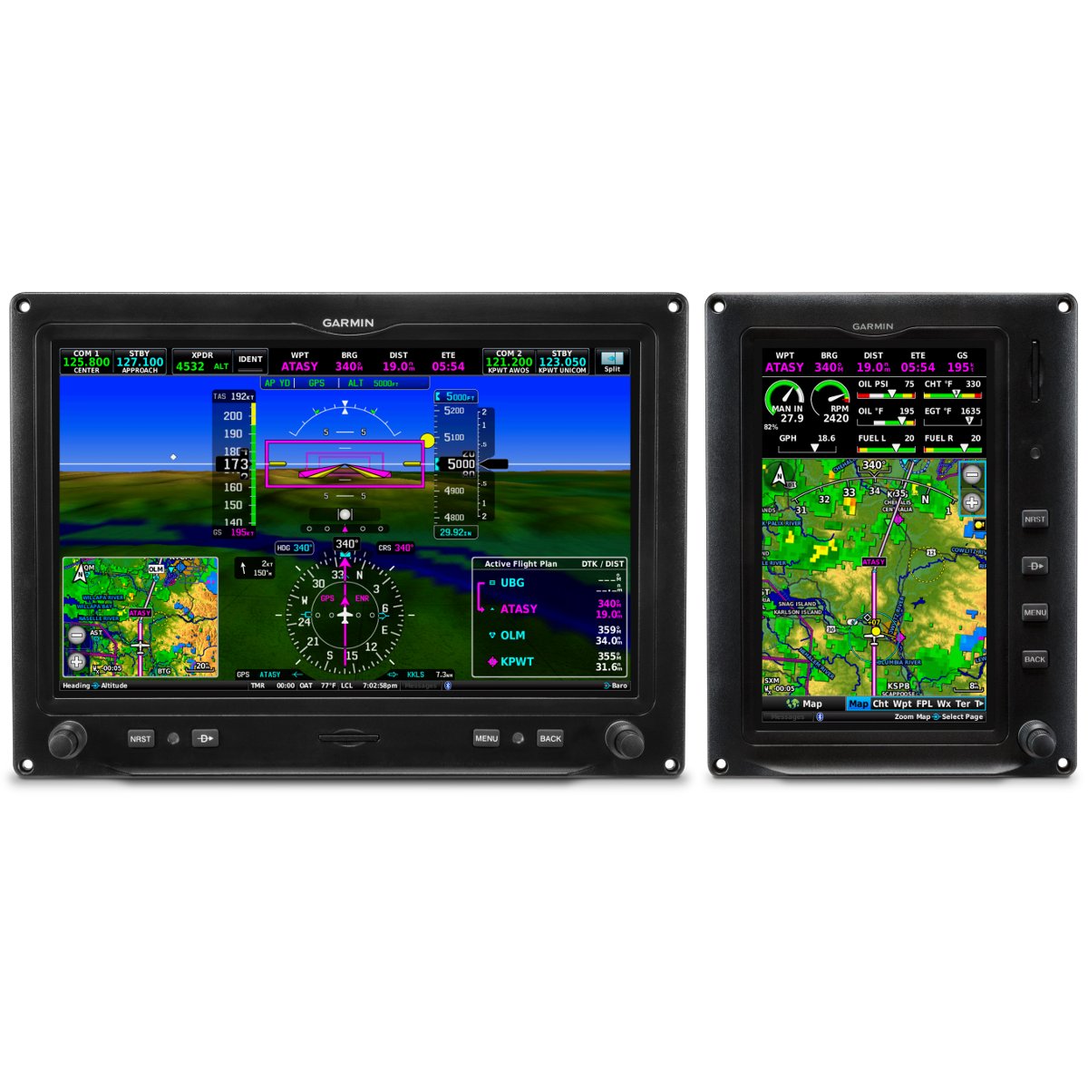
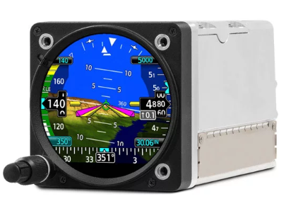
Garmin Introduces G5 Dg Hsi For Certificated Aircraft
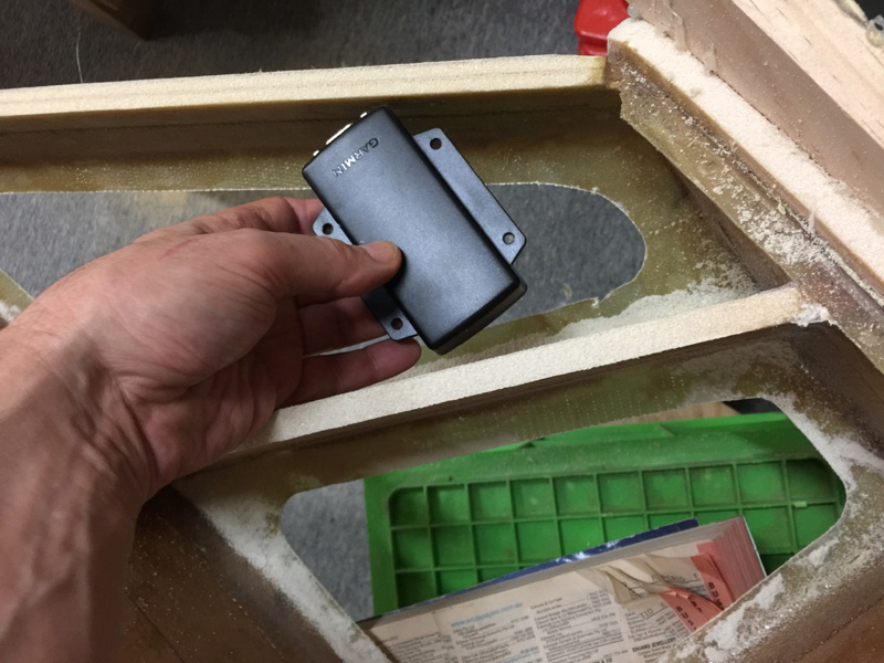
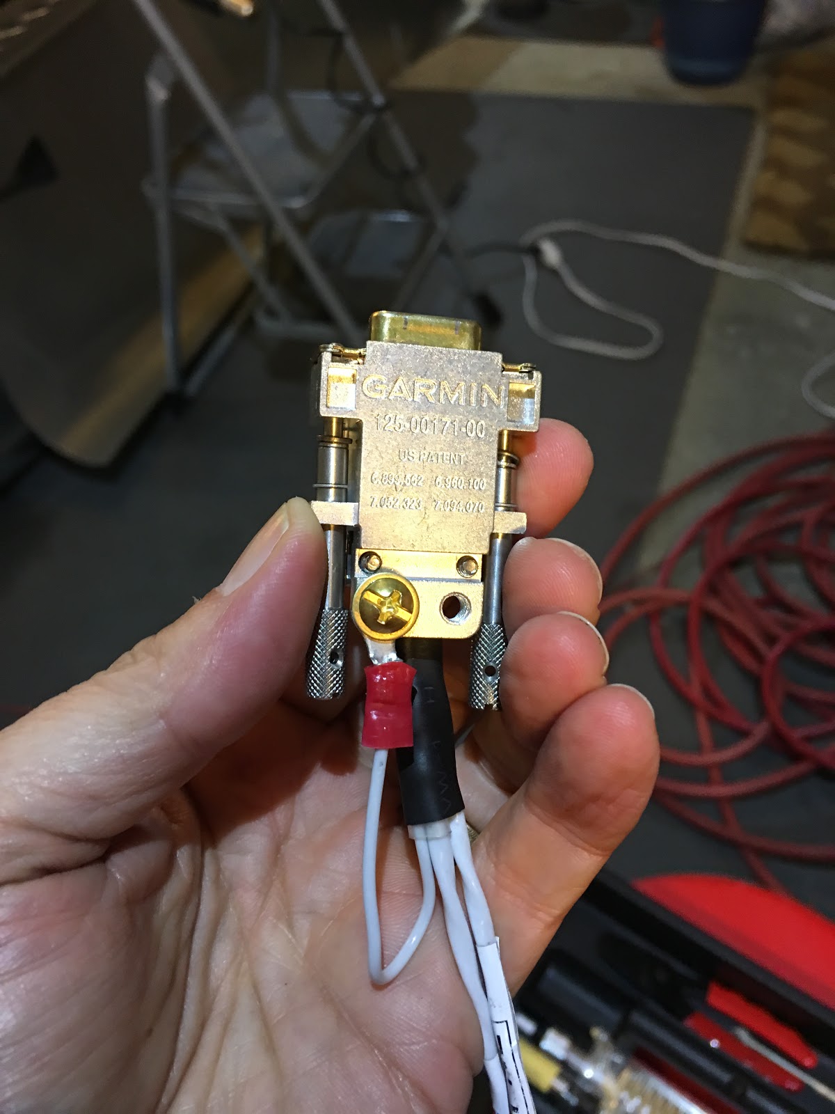
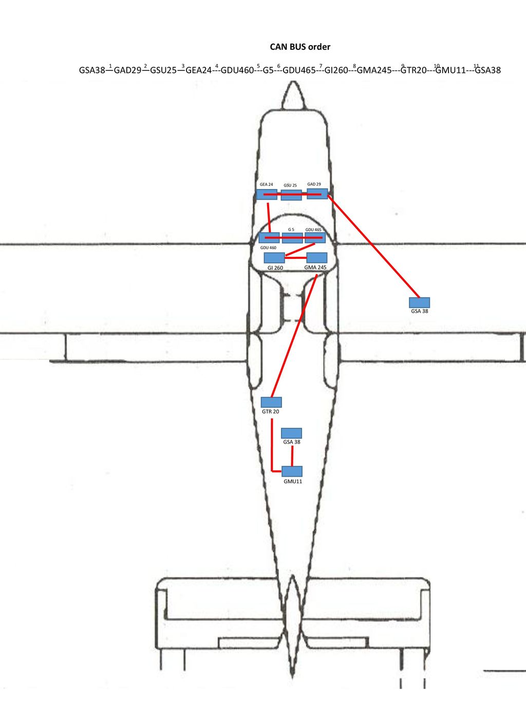
Garmin gmu 11 wiring diagram. 6 04 26 2017 updated gad 29 and gmu 11 part numbers 7 06 20 2017 updated gmu 11 gad 29 dimensions and emi test harness 8 10142017 revised to cover changes associated with the addition of the g5gad 29b third party autopilot interfaces. 011 03002 00 includes the following. Cast connector backshell with hardware can bus terminator 9 pin d sub connector 9 size 20 d sub socket contacts q. Gmu 11 is an affordable microprocessor based magnetometer. It can be used to accurately sense the earths magnetic field alignment and provide this data to compatible adahrs processors for use in referencing aircraft magnetic heading. Nmea 0183 connection diagram.
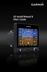
This area intentionally blank. Section 14 gmu 11 magnetometer installation. I have a g5 experimental version. Garmin g3x wiring fundamentals series can bus pass through node termination solder method. E garmin g5 install manual pilots guide. In essence the magnetometer acts as an electronic compass showing the adahrs which direction the aircraft.
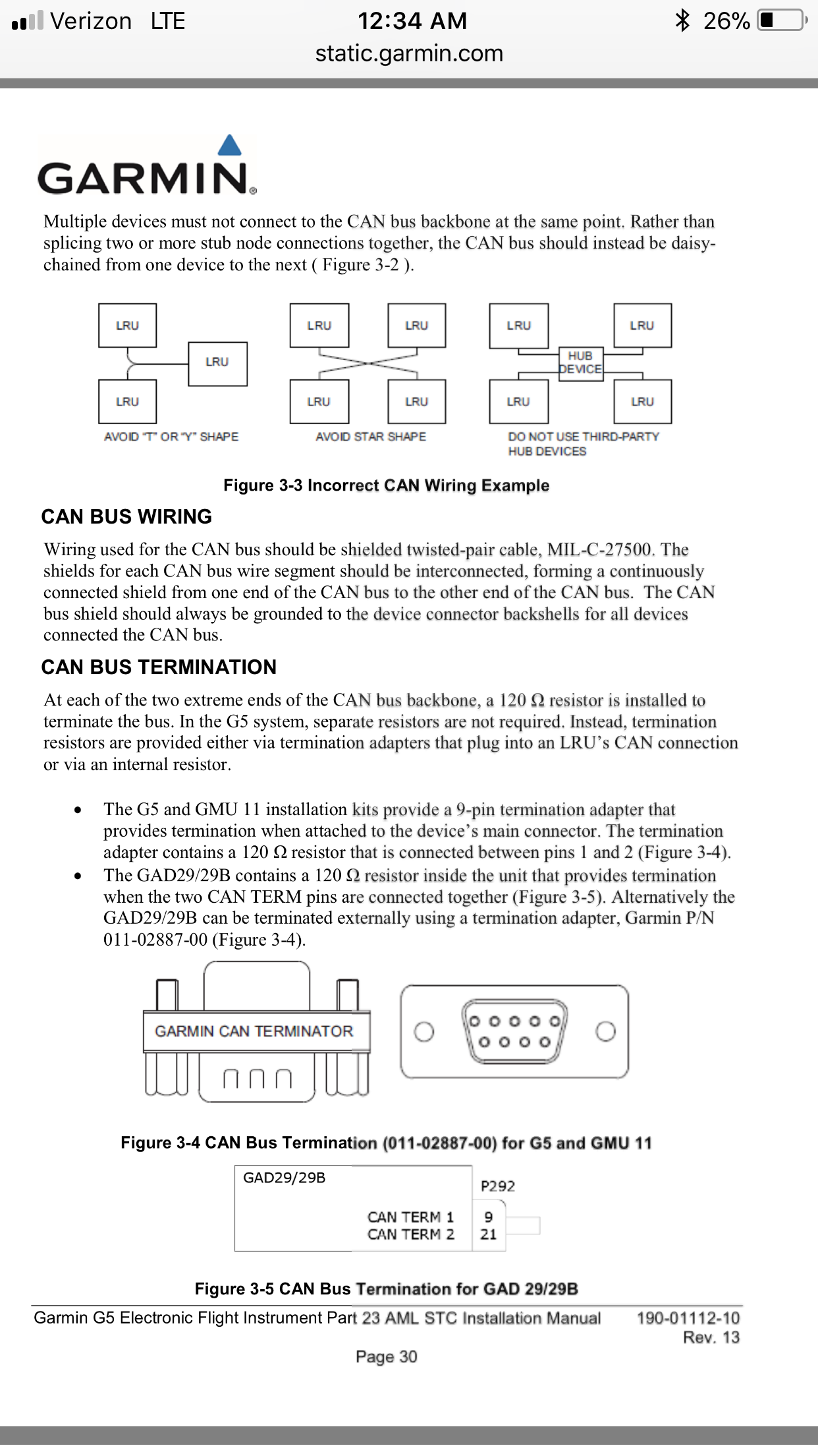
Garmin support center is where you will find answers to frequently asked questions and resources to help with all of your garmin products. View and download garmin g3x touch installation manual online. G3x wiring fundamentals video 5 of 10. Correct can wiring example. Incorrect can wiring examples. G3x touch avionics display pdf manual download.
12 vdc power source wiring harness nmea 0183 compliant device item garmin wire function garmin wire color nmea 0183 device wire function power red power ground black data ground tx.
Gallery of Garmin Gmu 11 Wiring Diagram