Remember that the hot black or red wire goes to the brass colored screw neutral white to the silver screw. Ceiling fan wiring diagram.
Wiring Diagram A Comprehensive Guide
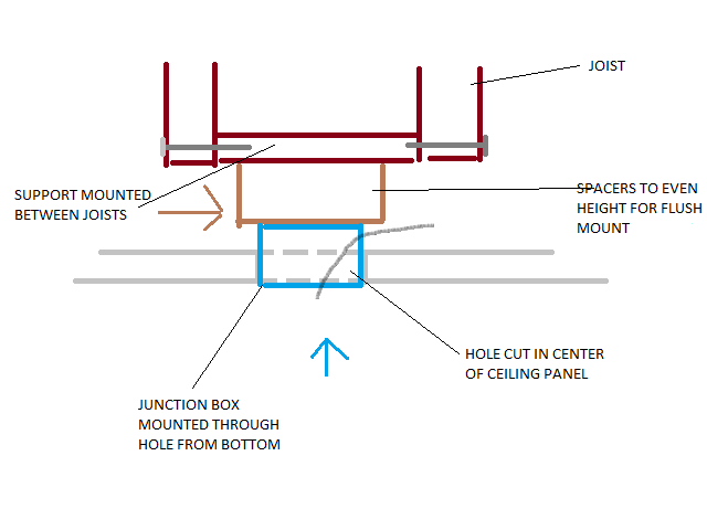
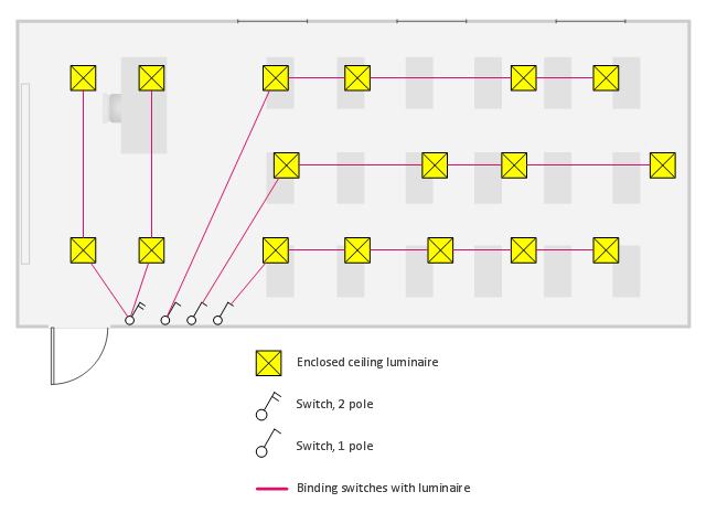
False ceiling wiring diagram. Wiring diagram 1 power enters at the wall switch box. Mount the electrical box in the ceiling with more madison bars and screws. To read a wiring diagram initially you need to know exactly what essential components are consisted of in a wiring diagram as well as which photographic icons are utilized to represent them. The common elements in a wiring diagram are ground power supply cable and link output gadgets buttons resistors reasoning gate lights and so on. 2 two way switch 1 fan regulator ceiling fan wiringकस करत ह द ट व सवच सलग फन वयरग duration. Wire the new fixture in the box and mount it to the ceiling.
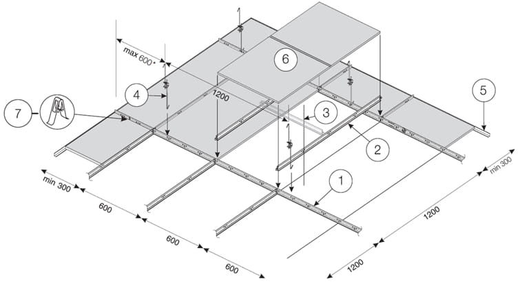
Run the cable through the clamp and tighten it down. With these diagrams below it will take the guess work out. Hanger wire service tiles border tiles walls field tiles 2985mm 1335mm main runner connection diagram 10 diagram 11 a wall to wall with field and border tiles this is one of the most important step before commencement of actual ceiling installation. Open it pop the plug out of one of the wire holes and thread a wire clamp into it. Take a closer look at a ceiling fan wiring diagram. If there is a bare ground wire in the fixture often found in ceiling fans and exterior fixtures twist it together with the ground wire from the cable and put a wire nut on it.
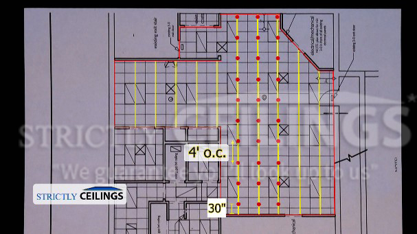
Here grid layout is arrived by. Whether you are looking to wire a ceiling fan with lights to one power switch or add a fan in a room without a switch source this guide will teach you how to wire a ceiling fan using four common scenarios and the best wiring methods. Installing a ceiling fan. Turn the power back on. Scott installed the boxie ceiling mounted led fixture manufactured by tech lighting. Wiring ceiling fans can seem complicated but the task really just depends on the type of fan you are installing and how you want it to operate.
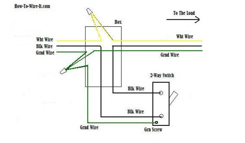
This might seem intimidating but it does not have to be. Patch the wall where the temporary hole was cut. There will be a cover on the connection box that fastens with a small screw. Power starting at the switch box this wiring diagram shows the power starting at the switch box where a splice is made with the hot line which passes the power to both switches and up to the ceiling fan and light. Pick the diagram that is most like the scenario you are in and see if you can wire up your fan. Switched lines and neutral connect to a 3 wire cable that travels to the lightfan outlet box in the ceilingthe fan control switch usually connects to the black wire and the light kit switch to the red wire of the 3 way cablein this diagram the black wire of the ceiling fan is for the fan and the blue wire.
Splice the black and white cable wires to the fan wires using a wire nut. Line voltage enters the switch outlet box and the line wire connects to each switch.
Gallery of False Ceiling Wiring Diagram