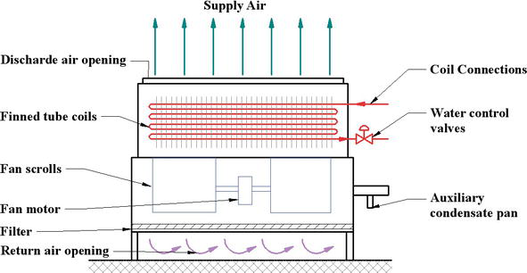
Thermostat wiring diagrams heat pumps are wired for hvac control far differently than air conditioning systems so make sure you know the difference and correctly identify the type of hvac system you have installed. Primary drain pan high level sensor hhws 0 fcu control diagram not to scale filter supply fan t occupancy sensor notes.
L377 Vaq Raq First Co
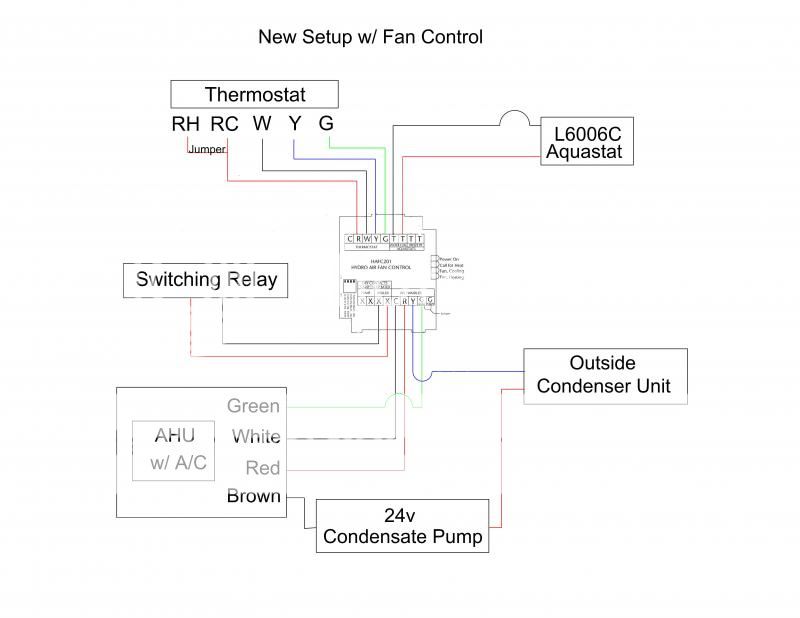
Fcu control wiring diagram. Fcu digital controller provided by mscc. Fcu fan coil unit control system solutions. The information herein provides guidance on how the product should be installed operated and maintained. Fan coil relay board fcrb installation operation and maintenance. 2 icp das co ltd. No rl2 rl3 rl4 rlcom switch ac in gnd vs d d gnd d d vs gnd d d vs thermister low medium high 2 way 3 way valve 1030v.
Fan coil unit fcu fan motor control. Wiring diagram fcu tpd series thermostat sc series 4 ch relay board rl1com rl1nc rl1. These installation operation and maintenance instructions relate solely to the cheetah fan coil unit product as manufactured by caice acoustic air movement ltd. 1the mechanical systems control contractor mscc shall be responsible for the selection of providing installing all ddc controllers control devices to accomplish the sequence of. Additionally before you decide to change your thermostat make sure you have the correct tools especially a screwdriver and wire pliers. Example wiring diagrams typical 24vac control drawing refer to unit control enclosure for actual order specific drawings eti fcu fcrb installation operation and maintenance.
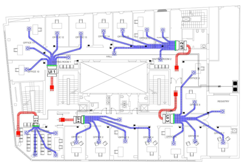
Direct digital control system index of drawings sheet description 1 title and cover page 2 supervisory controller 3 fcu wiring 5 ahu flow diagram 6 ahu 1 wiring diagram cover page pittsburgh air systems inc.
Gallery of Fcu Control Wiring Diagram