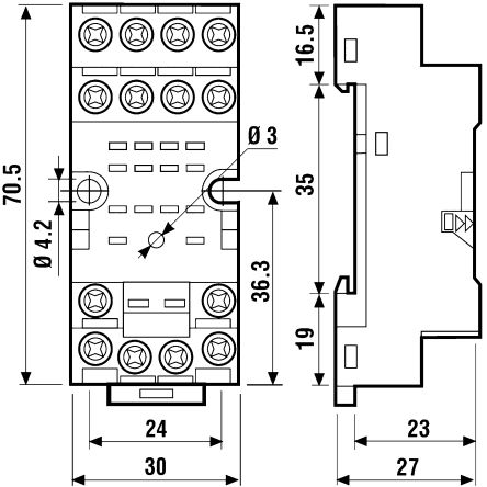
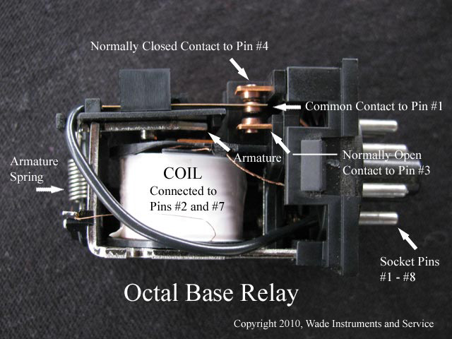
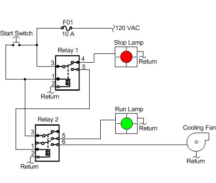
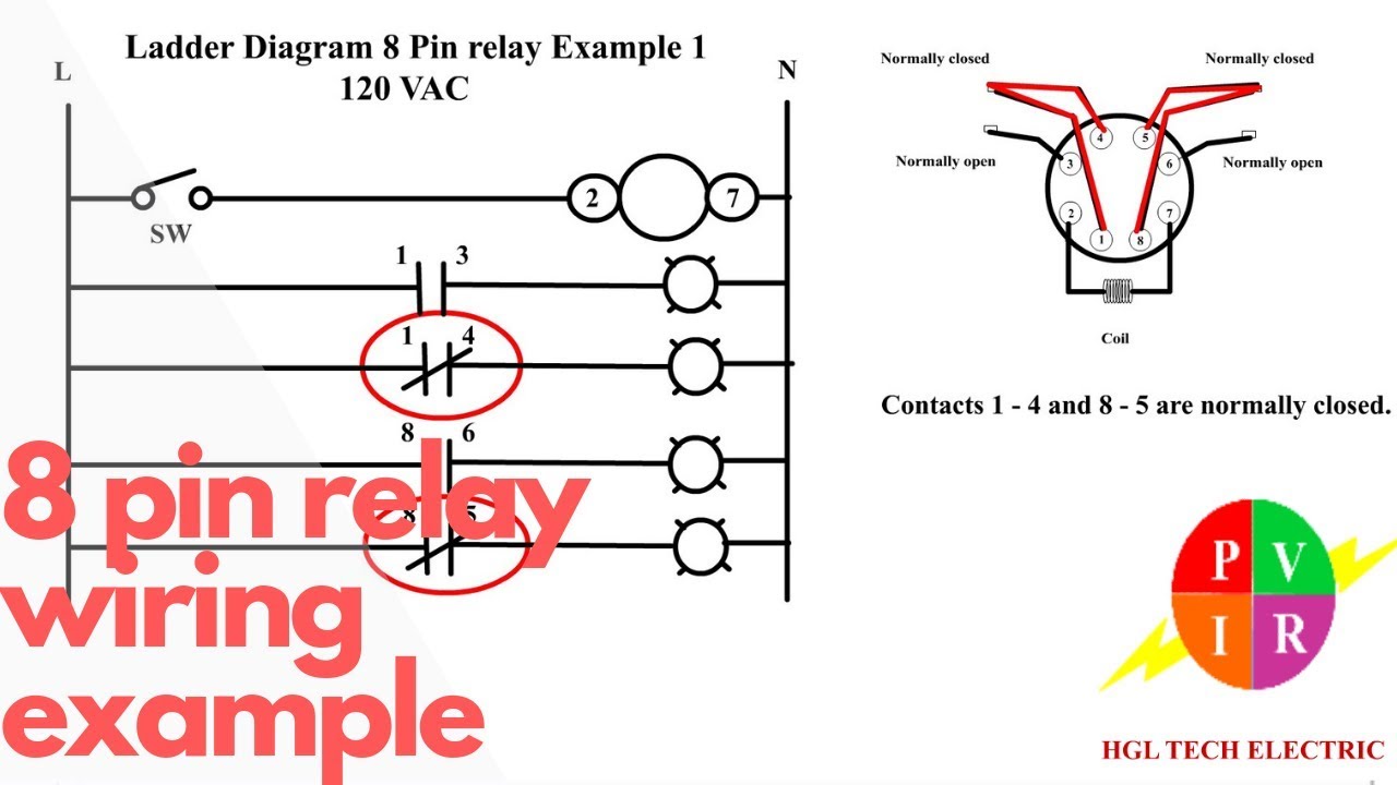
The example relay diagrams below show how a relay works. The square relay pinout shows how the relay socket is configured for wiring.
8 Pin Relay Wiring Relay Connection 8 Pin Relay Connection Electrical Relay
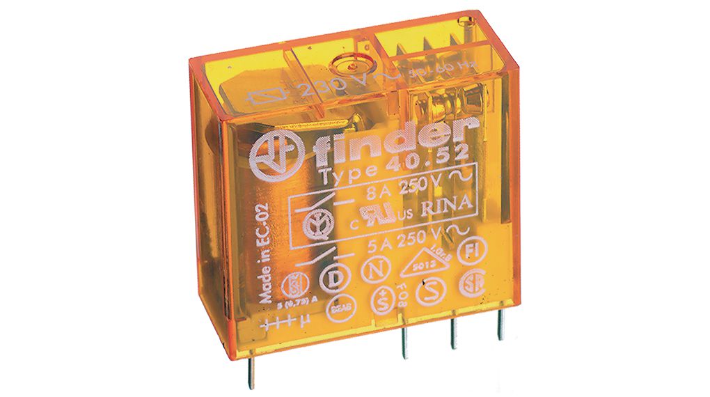
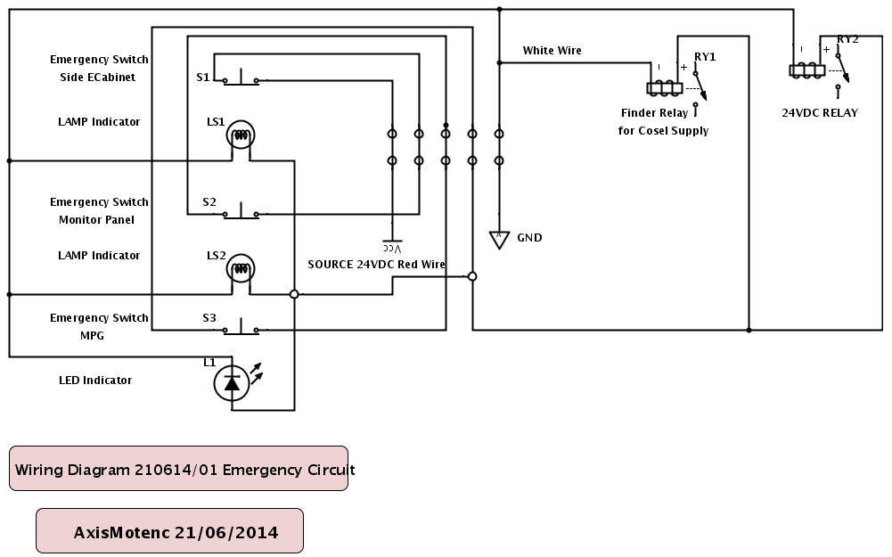
Finder relay wiring diagram. Interruption of a circuit without any specific requirements for distance or dielectric strength across the contact gap. When a relay contact is open this will switch power on for a circuit when the coil is activated. They commonly use an electromagnet coil to operate their internal mechanical switching mechanism contacts. This pinout image is only a 2 pole diagram for room on the page purposes but you can get the picture here with this one since a 3 pole will just have 1 more set of contacts. 10 a general purpose relay. A wiring diagram is a simplified traditional pictorial depiction of an electrical circuit.
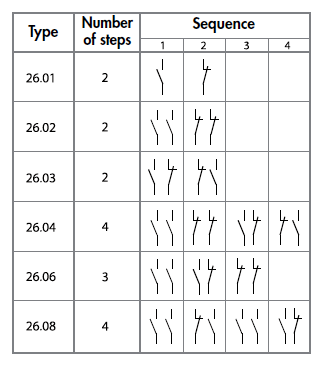
In this case when the test button is pushed the contacts operate. A 8 pin relay wiring diagram or 8 pin finder type relay connetion diagram. A 8 pin relay wiring diagram or 8 pin finder type relay connetion diagram. Same effect can be achieved by wiring two single contacts in series. 14 pin relay base wiring diagram finder 14 pin relay socket diagram in this post you will learn about the 14 pin relay base wiring diagram. On the relay we have the wiring diagram in which all terminals shown with its working principles.
As i said above that in relay we have 14 pin which is numbered form 1 to 14. This is also called 8 points glass type relay. Assortment of 12 volt relay wiring diagram. Case 1 the plastic pip located directly above the test button remains intact. This is also called 8 points glass type relay. The dual purpose finder test button can be used in two ways.
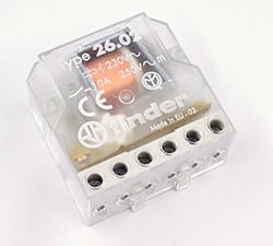
Finder relays types 4591 56xx 0300 62xx 0300 and. It reveals the components of the circuit as simplified shapes and also the power and signal connections in between the tools. When the test button is released the contacts return to their. A relay is an electrically operated switch.
Gallery of Finder Relay Wiring Diagram