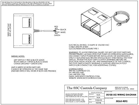
56 mmø diameter mounting holes on 2 78 in. February 19 2019 by larry a.
Lincoln Foot Pedal Wiring Diagram Tig Welder Foot Pedal
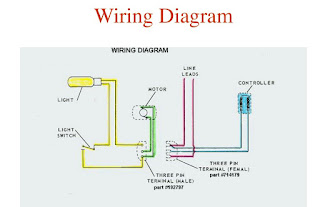
Foot pedal switch wiring diagram. If you think its possible any idea where i can find a wiring diagram for the r tech pedal. A wiring diagram is a streamlined conventional pictorial depiction of an electrical circuit. Collection of foot switch wiring diagram. Following your post of the schematic. Btw you can get lamp switches at ace hardware cheap. To wire the actuator to the foot switch for double action extentionretraction make the connections between the foot switch power source battery relay and actuator wires as follows.
I used an old extension cord and cut a short piece for the socket side. The wiring colors in the usa are black for hot white for neutral and green or greenyellow for ground. Clipper foot operated switches are furnished with two 732 in. Foot switch wiring diagram above is a simple diagram that shows how things get wired. Foot switch wiring diagram. It shows the parts of the circuit as streamlined forms and the power and also signal connections between the gadgets.
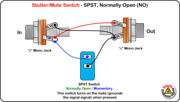
H 10 locknut clipper foot switch 522 b14 full guard with assembly. A wiring diagram typically gives details concerning the loved one position as well as setup of gadgets as well as terminals on the tools to assist in structure or servicing the gadget. Use two number 10 machine screws and two number 10 lock nuts when mounting foot switch to full guard. Shield is ground and goes to the sleeve of the trs plug and to one side of each switch one wire to each switch and the other end to the left over connectors on the plug. Instead with the pedal disconnected from the welder attach a power supply say 5v or a 9v battery you can translate that to foot pounds if you find that more intuitive. Building one without leds is seemple.
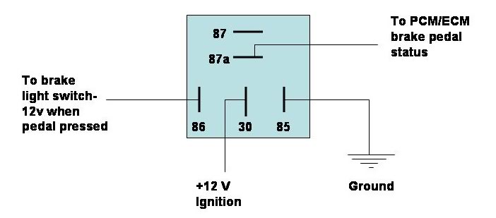
Connection to relay terminal 4 nc relay terminal 14 t2 battery negative terminal connection to battery positive terminal battery negative terminal actuator terminal 2 black foot switch up wire battery positive terminal actuator terminal 1 red battery. 2 wire plus shield cable 2 onoff switches a box and a trs plug. See diagram c form 522 f20 rev.
Gallery of Foot Pedal Switch Wiring Diagram