Assortment of go go scooter wiring diagram. The gogogate product and our door sensors are meant to be used with garage door openers equipped with photoelectric safety sensors manufactured after 1993.

Gogogate2 Garage Door Remote Opener Installation
Gogogate wiring diagram. This is where you will insert the wireless usb adapter. These sensors are normally found at the bottom of your garage door and avoid accidental closing of your garage door if an object or person is on the path of the door. Introduce the authentication code found in the quick start guide of your gogogate2 device. Turn on wi fi on your smartphone look for the gogogate network and connect to it nb. Read the above terms and conditions. The card is used to operate your gogogate and also for future software upgrades.
The gogogate product and our door sensors are meant to be used with garage door openers equipped with photoelectric safety sensors manufactured after 1993. Check the box to accept terms and conditions 7. Step 2 connect ggg2 wds to gogogate2 device step 3 programming sensor during gogogate initial installation door 1 door 2 door 3 123456 78901. Connects the 3 pre assembled garage cables to your garage door wall buttons. It should not be removed while the device is powered on. These sensors are normally found at the bottom of your garage door and avoid accidental closing of your garage door if an object or person is on the path of the door.
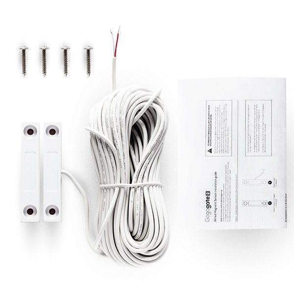
Ultimate gate kit datasheet. Gogogate is an open network generated by the device itself no password required. Open the gogogate app and select add begin your installation wi fi. Gogogate 2 wireless sensor. Gogogate 2 wired sensor. If you have enabled door 3 use cables out of terminals 5 and 6.
Select your gogogate device and fill all the fields in a 3 simple steps process. It shows the parts of the circuit as simplified shapes as well as the power and signal links between the devices. Sd memory card slot. If you have enabled door 2 use cables out of terminals 3 and 4. If you have enabled door 1 use cables out of terminals 1 and 2. A wiring diagram is a streamlined standard pictorial representation of an electric circuit.
Gallery of Gogogate Wiring Diagram