Minn kota trolling motor with i pilot link and built in mega imaging 1 bow mounted humminbird unit and 1 console mounted humminbird unit. Download diagram 2 for.

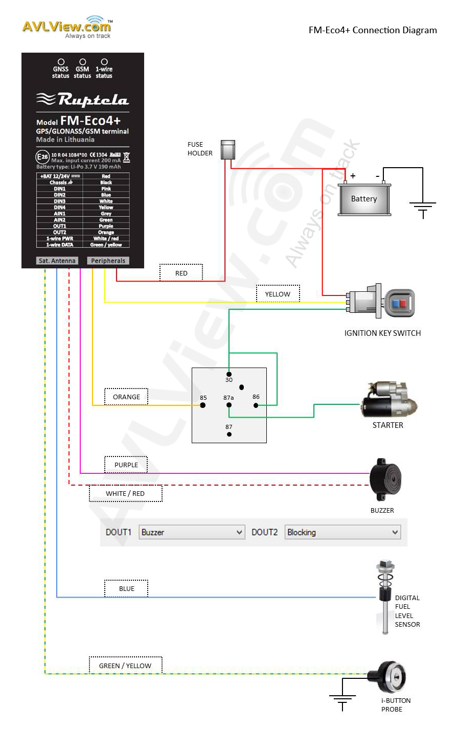
Vehicle Gps Tracker With Relay Installation Wiring Diagram
Gps wiring diagram. Make sure all wires are routed neatly throughout the dash. Garmin gpsmap marine gps receiver pdf user manuals. Solder the powerdata cable data out to the receive data rxd pin 2 of the db9 db25 pin 3 4. A wiring diagram is a simplified traditional pictorial depiction of an electrical circuit. Dos and donts of gps tracking installation do. Appropriate wire connectors for the assembly as opposed to soldering the connections.
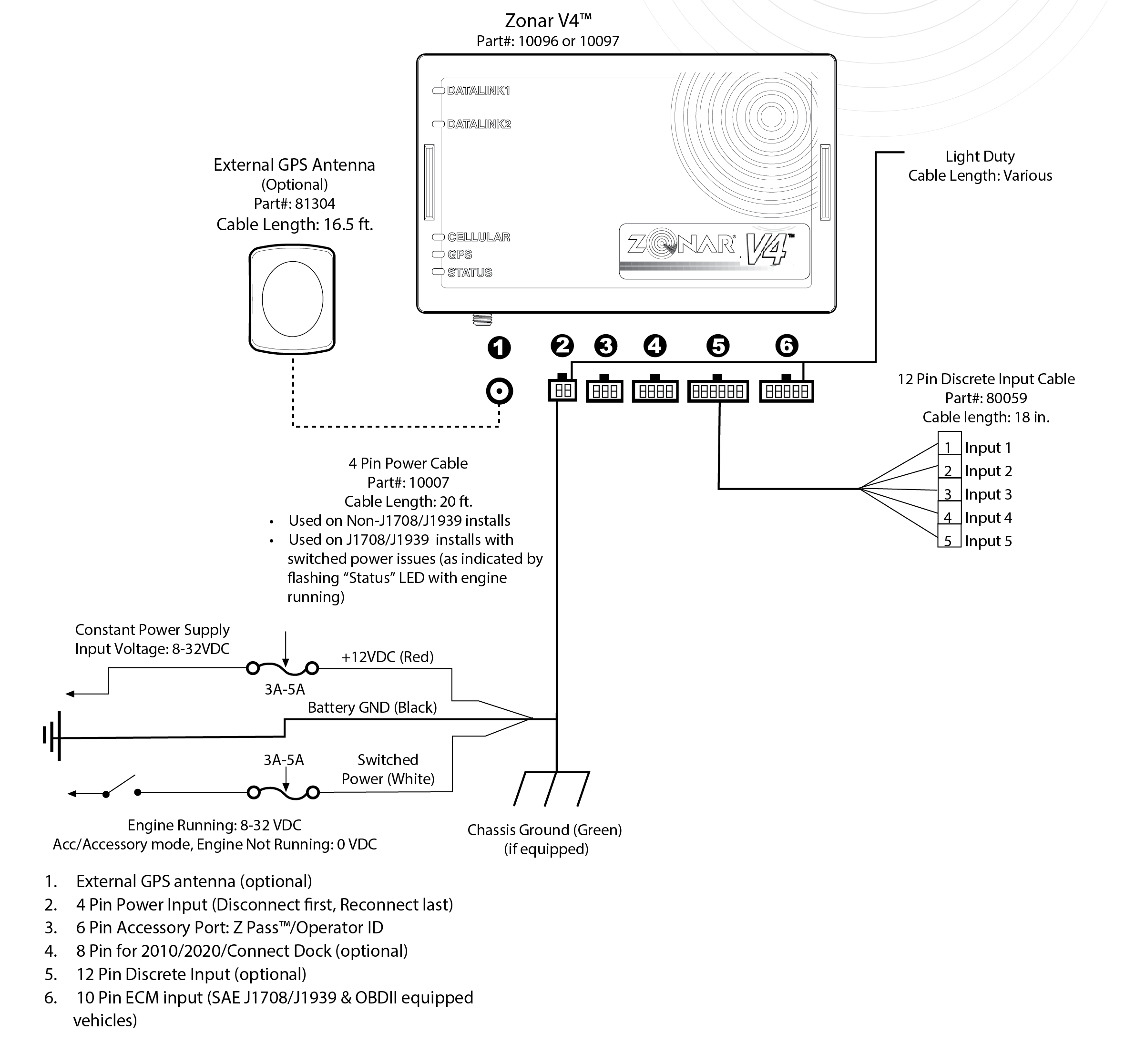
Calamp lmuxx install guide available wiring harness the lmuxx ships with the 5c wiring harness. View online or download garmin gpsmap marine gps receiver owners manualgarmin gps to pc wiring instructions introduction this will outline the basics for connecting most. The 5c is an optional cable with multiple connectors for standard io. Refer to the wiring diagram on pages 3 4 which applies to your gps units type of interface connector. Choose a mounting location high in the dash with no metal obstructions above the device. Assortment of passtime gps wiring diagram.
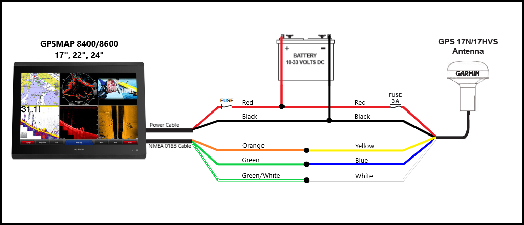
Passtime gps wiring diagram. Humminbird bow unit and 1 console unit networked together with heading sensor gps puck and high speed transducer with y cable. It reveals the elements of the circuit as simplified forms and the power and also signal links in between the gadgets. This harness requires hard wiring of the power ground and ignition wire. The wiring diagram for the gps19x dosent match the color coding on the power cable that garmin sold me for the. Make sure to verify all connections with a multimeter.
Here is a link to find vehicle wiring diagrams.
Gallery of Gps Wiring Diagram