Wellborn collection of ground fault receptacle wiring diagram. March 31 2019 by larry a.
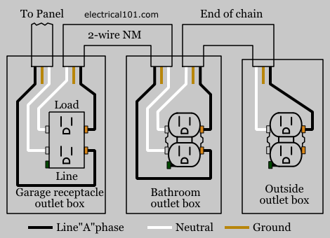
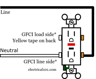
Gfci Load Wiring Electrical 101
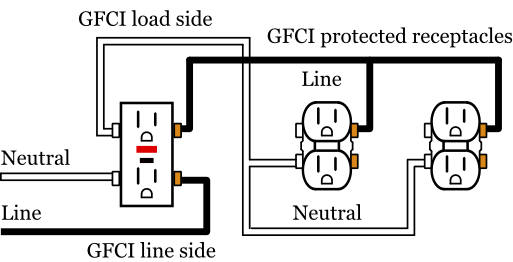
Ground fault wiring diagram. It shows the components of the circuit as streamlined shapes and the power as well as signal connections in between the devices. It means all the connected loads to the load terminals of gfci are protected. Ground fault circuit interrupters gfcis gfci load wiring. This diagram illustrates the wiring for multiple ground fault circuit interrupter receptacles with an unprotected duplex receptacle at the end of the circuit. Refer to the diagram above about wiring gfci receptacles for additional help. Gfci load wiring diagram.
If more than 1 black and 1 white conductor are in the electrical box also loosen the load side silver and brass terminal screws. The load terminals on the gfci are not used and the last receptacle is wired directly to the circuit source. A wiring diagram is a simplified standard photographic representation of an electrical circuit. One side of the gfci connected to the ground neutral wire as shown white in the diagram and another side to the high potential hot wire shown as black in the diagram shows as in black color. Loosen the silver and brass terminal screws on the line side of the outlet. The above diagram shows the gfci wiring to multiple outlet as in white while the pictures are same.
In this gfci outlet wiring and installation diagram the combo switch outlet spst single way switch and ordinary outlet is connected to the load side of gfci. Arc fault circuit interrupters afcis. The toggle switch in the combo switch outlet controls the first light bulb while the single way.
Gallery of Ground Fault Wiring Diagram

%2BOutlet%2BWiring%2BDiagram.jpg)