The model gva 24 actuator may be mounted to the valve in four different positions fig. Housing o ring 116 plate.
Hayward Solar Pool Control Package
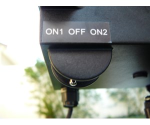
Gva 24 wiring diagram. Gva 24 valve actuator 2pc temperature sensor for 3rd input. Where to buy tweet. Reqd 1 glx gva 4scr mounting screws set of 4 8 8 1. Single pole may sound simple but there are different ways to wire a single pole switch. Valve actuator 24v 75a 15 ft. Occasionally your gva 24 goldlinehayward pool actuator will malfunction.
Move bypass dipswitch on heater circuit board to on position up. Refer to the diagram on the following page for a generic connection. The manuals supplied with most heaters also include specific wiring instructions for connecting the heater to an external control usually identified as 2 wire. Synchronous pivot 2. Diagram 2 shows wiring to a supported vsp and electric heat pump heater. Pool maintenance pool maintenance how a pool works opening your pool closing your pool.
To view these documents you will need to download the free acrobat reader which gives you instant access to pdf files. Cable item gva 24. These o ring seals are located at the top and bottom of the actuator where the shaft exits the actuator housing. Maintenance the gva 24 has two seals which should be lubricated every year. This guide shows you how to resolve some of the issues that prevent your valve actuator from performing correctly. The power can come from either the switch box or the fixture box and a set of electrical switch wiring diagrams will explain each of these scenarios to you clearly.
Switch nest right housing bushing. Cover bushing cam 2 screws 2 2 32 x 38 switch nest left. Gva 24 replacement parts. Click here to view the hayward gva 24 valve actuator. Switch wiring diagrams a single switch provides switching from one location only. The majority of our literature and brochures are in english only.
See diagramstables on the following pages to determine which configuration matches your system. Depending on the location of the common port where water enters valve and exit port where water leaves valve the cam settings may have to be changed. The top o ring requires the removal of the handle and the bottom requires that the gear train is disengaged. The pump must be locally programmed to run 24 hrsday at a fixed speed and the omnihub will turn it on and off based.
Gallery of Gva 24 Wiring Diagram