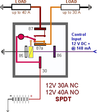
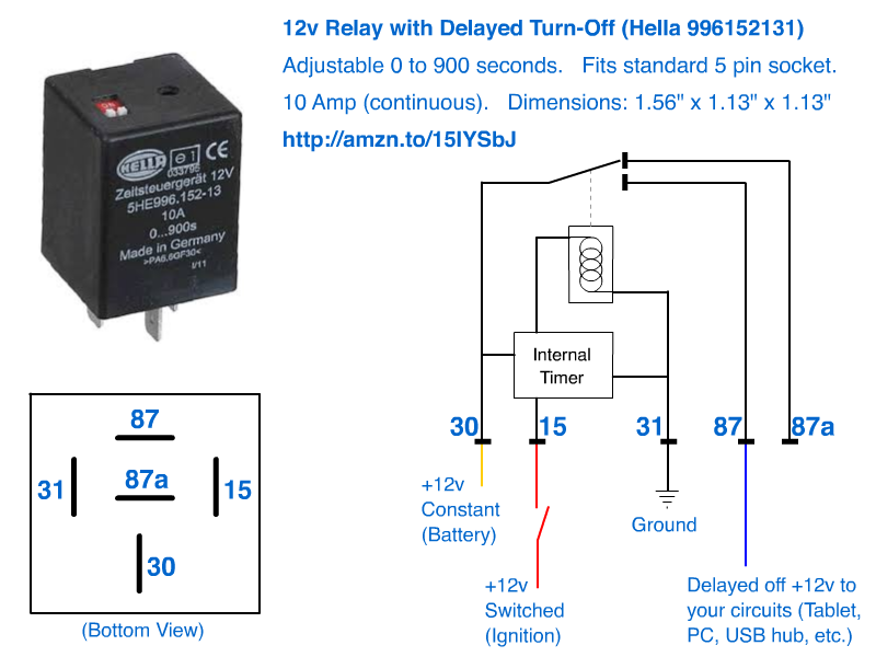
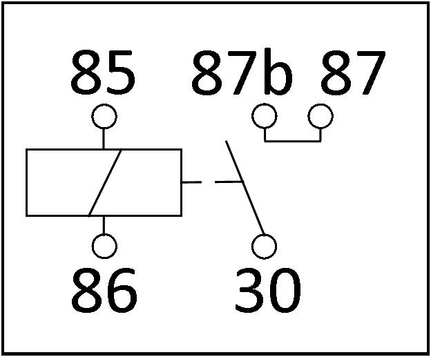
You will notice that on the type b layout pins 86 and 30 are swapped over compared with the type a layout. Hella valuefit 5 rd led.
Dave S Volvo Page Volvo Relays
Hella 5 pin relay wiring diagram. Hella valuefit 4 sq led 20. This video covers both 4 and 5 pin 12vdc relays. Hella valuefit 5 rd led. Current controlled relay for direction indicator lamps bi stable relay for switching between low and high beam. Hella valuefit 4 sq led 10. Hella valuefit 4 sq led.
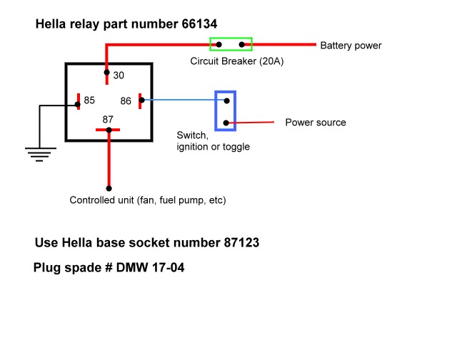
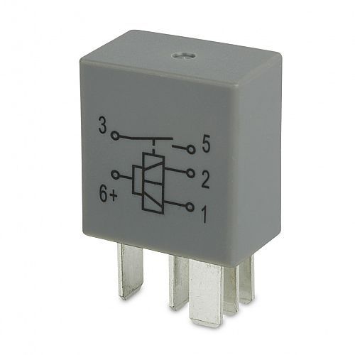
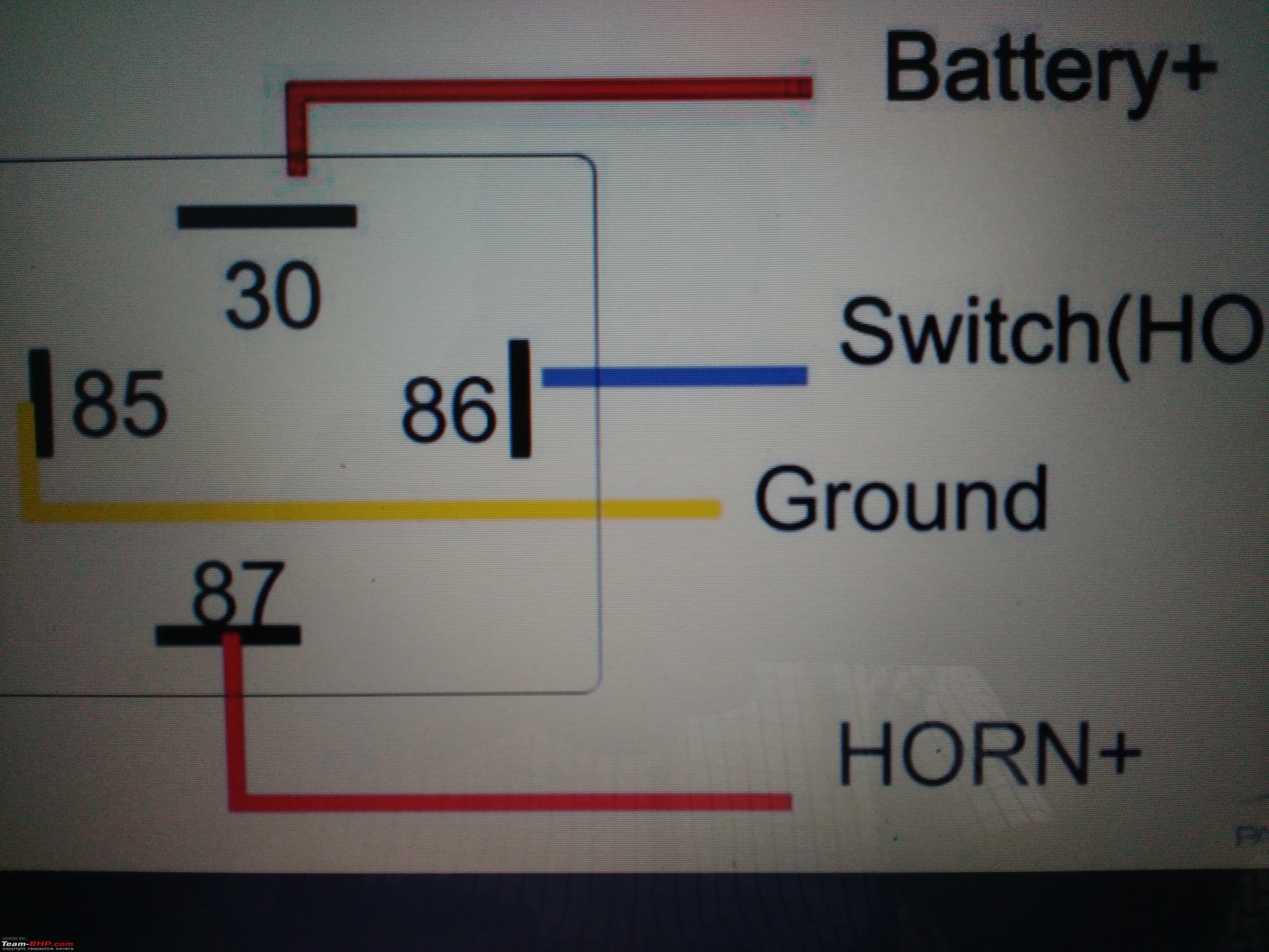
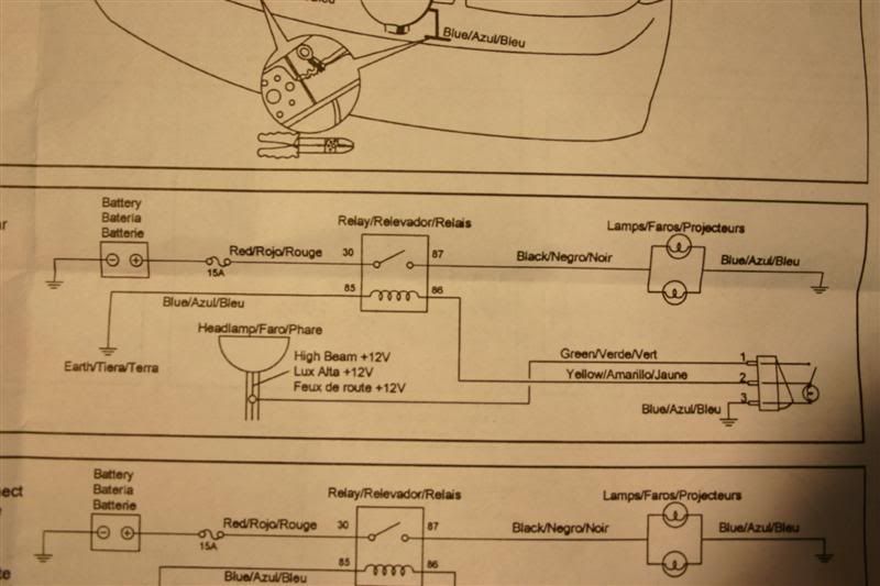
Four pin relays do not use this terminal see reference 2 under the common pin designations chart. Determine which wire leads to the second electrical device if equipped. When the coil is activated power will be switched from the normally closed pin to the normally open pin. I cover 34 and 5 pin relays and all you need is a 12v source a multimeter and a test light. Hella 4pin relay no c4003 12v c4002 24v terminal configuration 30 output 85 coil trigger 86 coil trigger 87 battery hella automotive relays s1 30 3 85 2 86 1 87 30 85 86 87 5 a fuse the hella disc horn set. Anyone have a hella 500 wiring diagram that i can take a look at or print up.
Diagram indicating wiringcurrent flow for hella b1910 disc horn set or b7424 trumpet horn set. Hella valuefit 5 rd led 20. Hella valuefit 5 rd led 20. Ultra beam led gen 2. Hella valuefit 2 led blu. In this video i show you how to wire a 12 volt automotive bosch style relay.
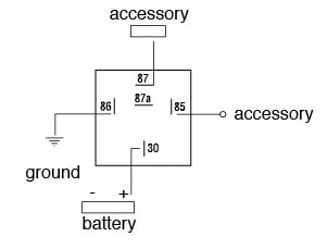
Hella valuefit rc360 gen 2. Slide this wires wire terminal onto a hella five pin relays terminal labeled 87a this terminal turns hot when the control circuit deactivates. Here is a video on how you can test a relay with or without a diagram. Multimeter used in video. Hella valuefit 4 sq led. Hella valuefit 2 led blu.
Hella valuefit rc360 gen 2. Nilight 10011w 16awg wiring harness kit 2 leads led light bar 12v onoff 5 pin rocker switch power relay blade fuse for jeep boat trucks 2 years warranty 1273 tyc 18 5715 90 9 toyota tacoma capa certified replacement right side marker. They have both normally open and normally closed connection pins. 5 pin relay 5 pin relays provide 2 pins 85 86 to control the coil and 3 pins 30 87 87a which switch power between two circuits. Ultra beam led gen 2. Hella valuefit 4 sq led 10.
The first modular system 1969 wipewash interval control unit 1970 k relay. The first fully electronic flasher unit 1968 l relay. Hella valuefit 5 rd led 10. Hella valuefit 5 rd led 10. 4 5 1951 first hot wire flasher unit 1960 a relay with metal housing. Hella valuefit 4 sq led 20.
Mechanical threshold voltage controller for windshield wipers 1965 e relay. The type b layout is arguably easier to work with as the connected terminals are in line making the wiring easier to visualise. These layouts are shown on the two 5 pin relays below pin 87a not present on 4 pin relays.
Gallery of Hella 5 Pin Relay Wiring Diagram