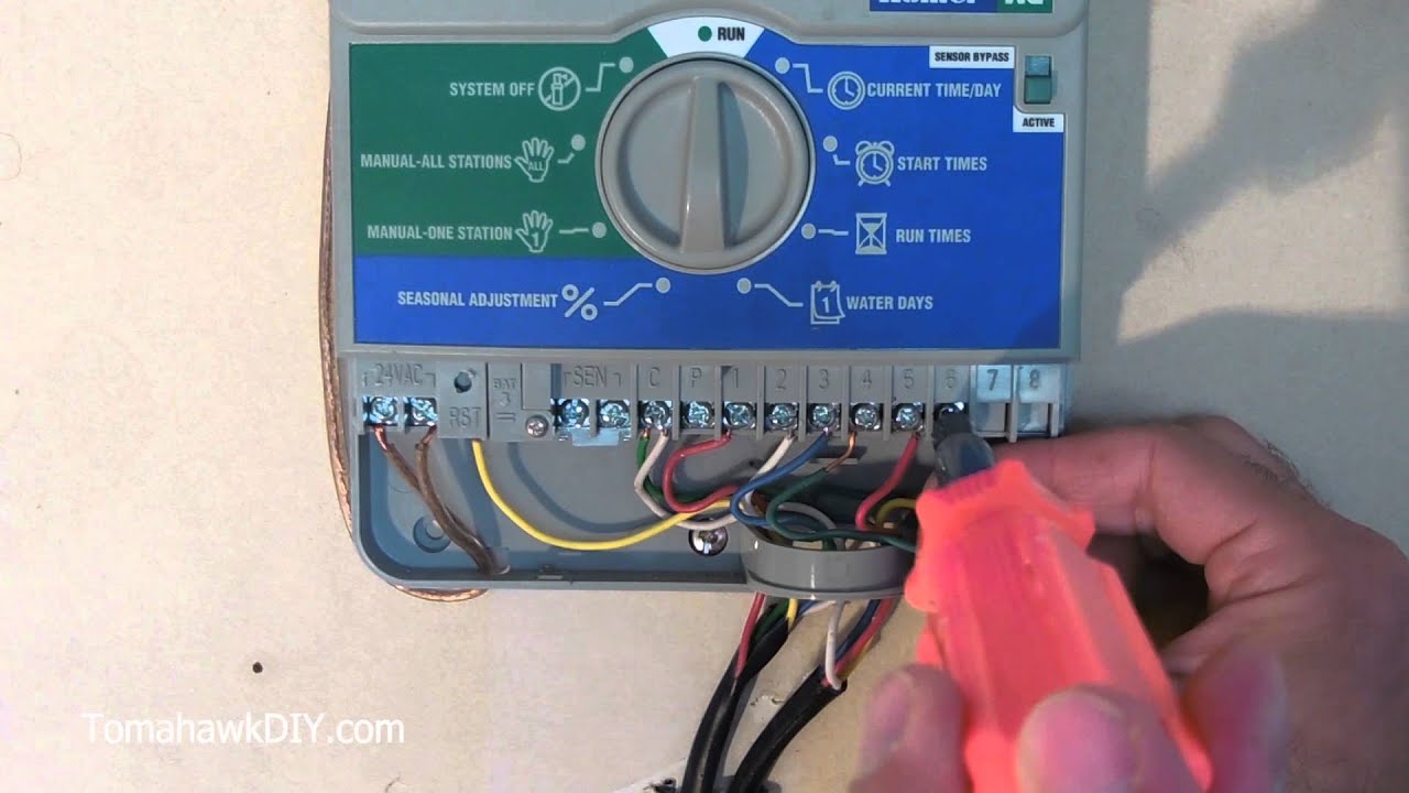
Owners manual and installation instructions product information hunter pro c owners manual and installation instructions 40 pages residential and light commercial irrigation controllers indoor or outdoor versions. This video is for hunter xc and hunter x core lawn irrigation controllers.

Wh 3441 85483 01 Wiring Diagram Hunter Free Diagram
Hunter src wiring diagram. Hunter 326 owners manual 2004pdf 116mb download. Available in a choice of three models to. This is video 2 of a 3 part series. Hunter 33 operators manual 2009pdf 132mb download. Hunter src wiring diagram wiring diagram is a simplified good enough pictorial representation of an electrical circuit. 5below is a typical drawing and description of a hunter src series timer masterpump valve wiring.
Hunters pump start relay psr has been created to provide that reliabilityas well as a lockable nema rated enclosureat an economical price. Zone wires 1 16 zone wires correspond to your landscapes zones. Terminal strip area use to attach transformer and valve wires from area shown in the diagram. Dish network wiring diagrams. Toyota hilux stereo wiring diagram. Hunter src wiring diagram.
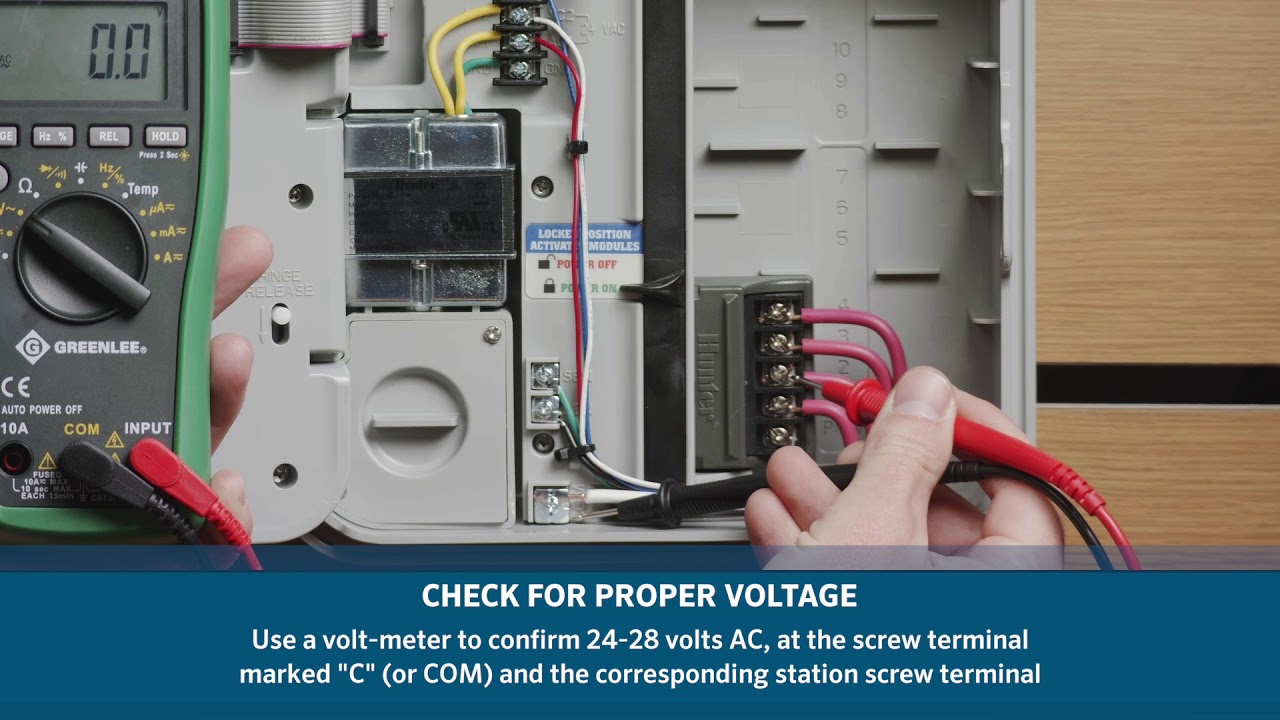
Over the life span of an src controller surges and electrical strikes can wear on the internal components of the srcs circuit boards. My hunter src controller reverts back to the current time display when i try to run a station what is wrong with my controller. Emg hss wiring diagram. We have 4 hunter pro c manuals available for free pdf download. If an extension to the wire provided is needed use the following table to. It shows the components of the circuit as simplified shapes and the faculty and signal links surrounded by the devices.
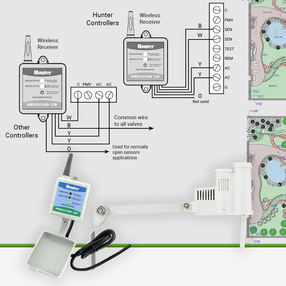
Vw golf mk6 wiring diagram. When a system requires the use of a booster pump or pulls water directly from a creek or pond its imperative to include a relay that can be counted on to activate the pump each and every time. Wiring an irrigation solenoid valve duration. 4 wire voltage regulator wiring diagram. Click here to view mounting instructions for the rain click transmitter. Before wiring your rain clik it is important to select an appropriate mounting location for the transmitter.
Basic wiring generation 2. 2011 f150 wiring diagram. The wiring bay of the rachio generation 2 includes terminals to house the common wire wires for each zone and advanced wiring components. Once the rain clik is mounted run the wire to the controller and fasten it every few feet with wire clips or staples for best results. Insert them into the blue numbered terminals. Most sprinkler timers will be similar to this example.
Access irrigation ltd.
Gallery of Hunter Src Wiring Diagram