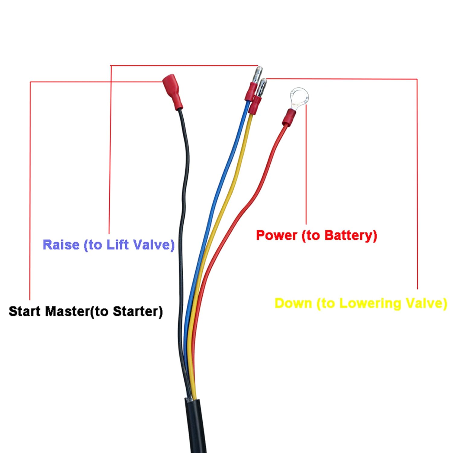
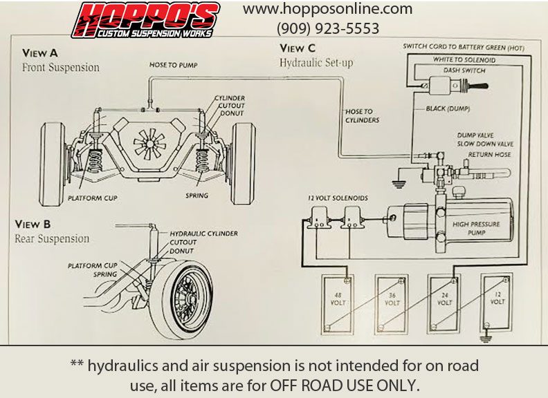
Wiring diagram for hydraulic set up on a car bradley powell. Wiring up the switches for the caddy part 1 and surprise.

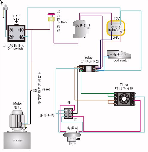
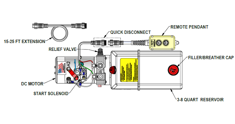
How To Wire Hydraulic Power Pack Power Unit Diagram Design
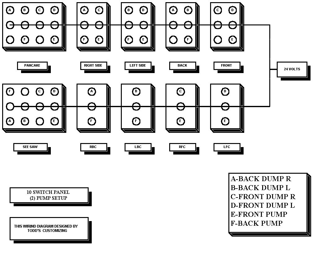
Hydraulic switch box wiring diagram. The box is constructed with quality smoked plexiglass for superior looks and durability. The 10 switch pre wired box is our most common switch box sold. Switchbox wiring diagram how to lowrider hydraulics. Higginbotham on saturday february 9th 2019 in category wiring diagram. If the liftgate is a gpt or 80 series open pump box cover. Showing a simple wiring diagram on a 4 battery 3 pump setup lowrider.
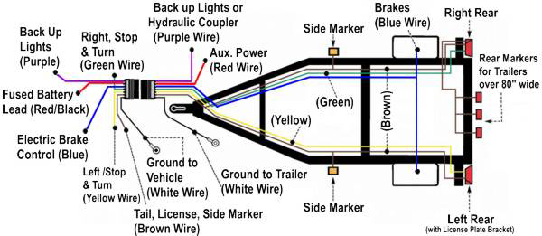
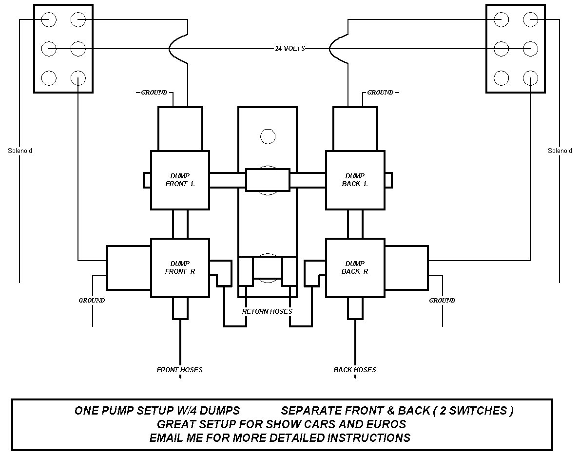
The box is wired for front back left side right side pancake front to back see saw front left front right backleft back right. How a lowrider hydraulic pump works duration. Here are some details of hydraulic pump electric diagram12vdc hydraulic power unit and 24vdc hydraulic power pack hydraulic circuit diagram and electrical diagram. Refer to gravity down lvts wiring diagram fig. The top of the box has custom printed labels on each individual switch that tell the move it performs. Three wire cable is supplying the source for the switches and the black and red wires are each connected to one switch.
See also electrical is this ceiling box wiring correct and how can i electrical switch wiring diagram from wiring diagram topic. How to wire dc hydraulic power pack unit. Wiring the switches on the caddy part 2. It is designed to be used on 2 3 or 4 pump hydraulic systems. It comes with a 13 foot switch cord that is perfect for most all installation applications. Cal wiring and hydraulic hoses.
10 switch pre wired box 2 3 4 pump only this is a fully labeled 10 switch box. The mounting guidelines of the chassis. Toggle switch wiring diagram hydraulic wiring diagram explained electrical switch wiring diagram uploaded by anna r. This diagram shows two switches in the same box with a separate 120 volt source feeding each. 6 switch wiring diagram regarding lowrider hydraulic wiring diagram by admin from the thousands of photos on the net concerning lowrider hydraulic wiring diagram we selects the best choices together with greatest resolution only for you and now this pictures is among graphics choices in this finest photographs gallery concerning lowrider hydraulic wiring diagram. It works with a 2 pump 3 pump or 4 pump setup.
And more a wireless remote connect wire drawing also show below for single acting hydraulic power packthis wireless remote can be with a quick connector can be changed with our standard. Mar 25 foot control cable along the lifting arm to the pump box and connect it according to the wiring diagram. Wiring two switches in one box with 2 sources.
Gallery of Hydraulic Switch Box Wiring Diagram