There are three ways to show electrical circuits. The uses of these two types of diagrams are compared in table 1.
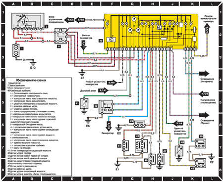
Mercedes W124 Wiring Diagrams Car Electrical Wiring Diagram
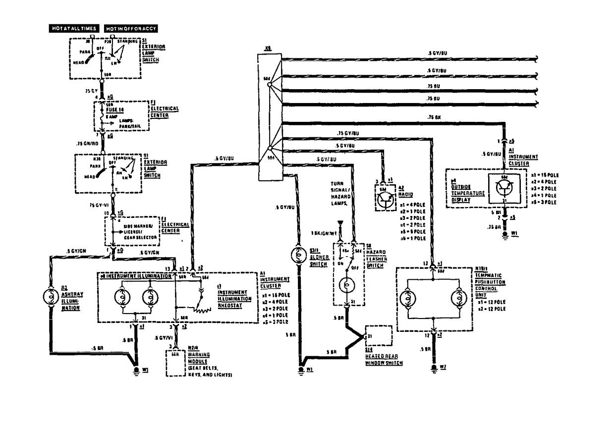
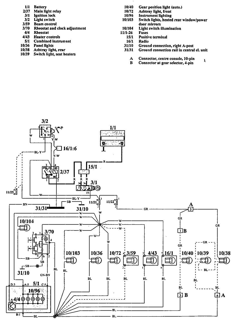
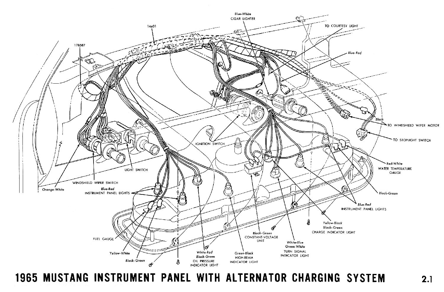
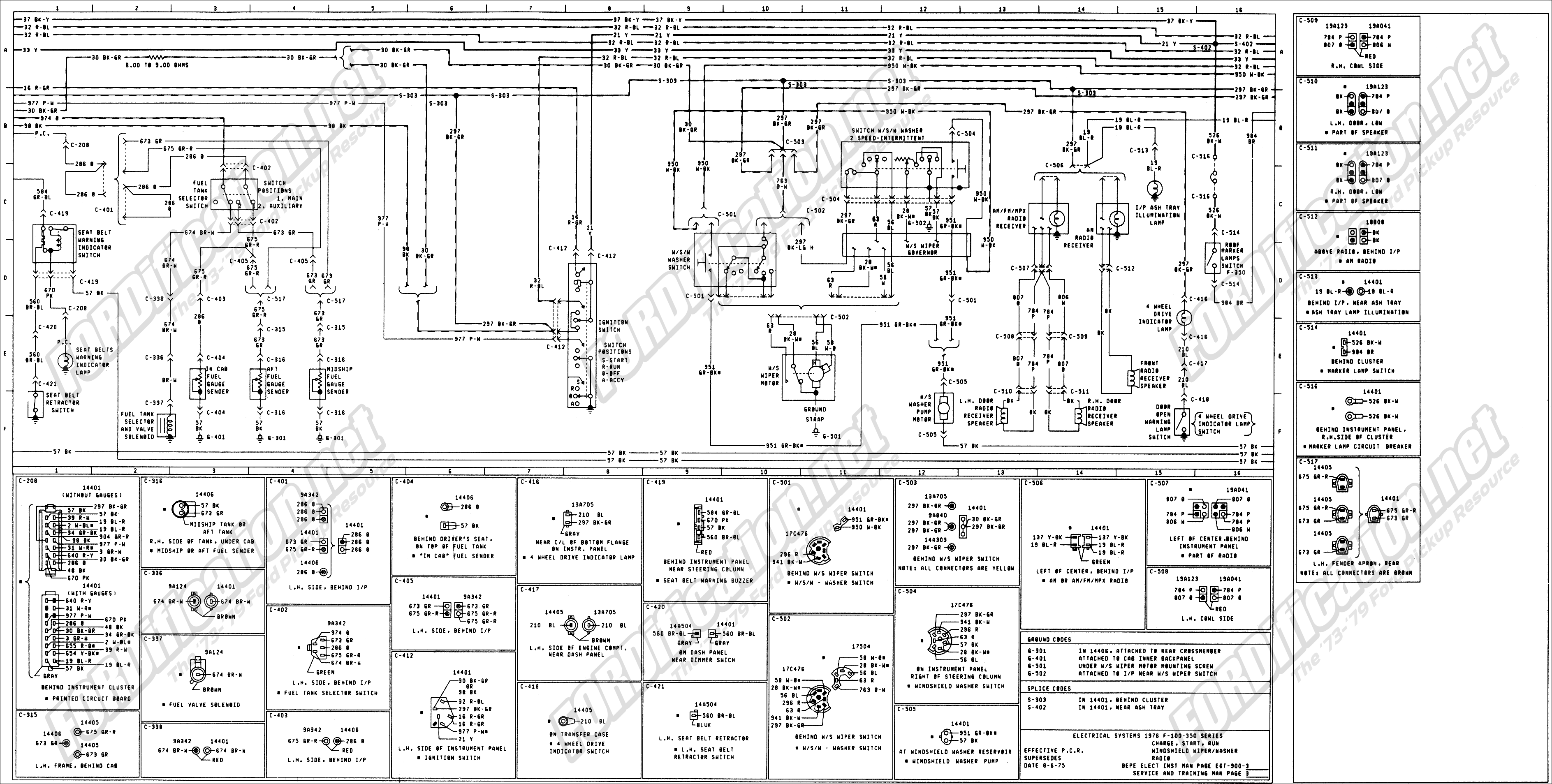
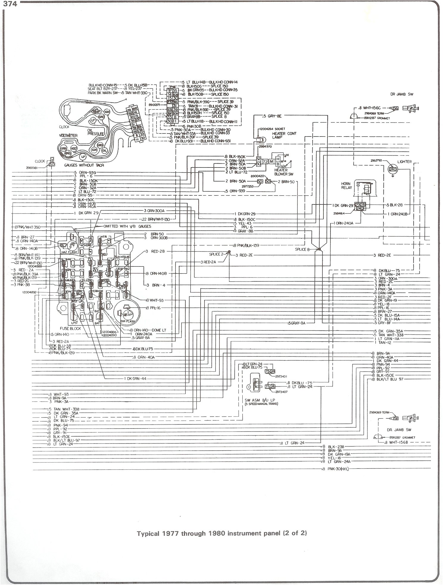
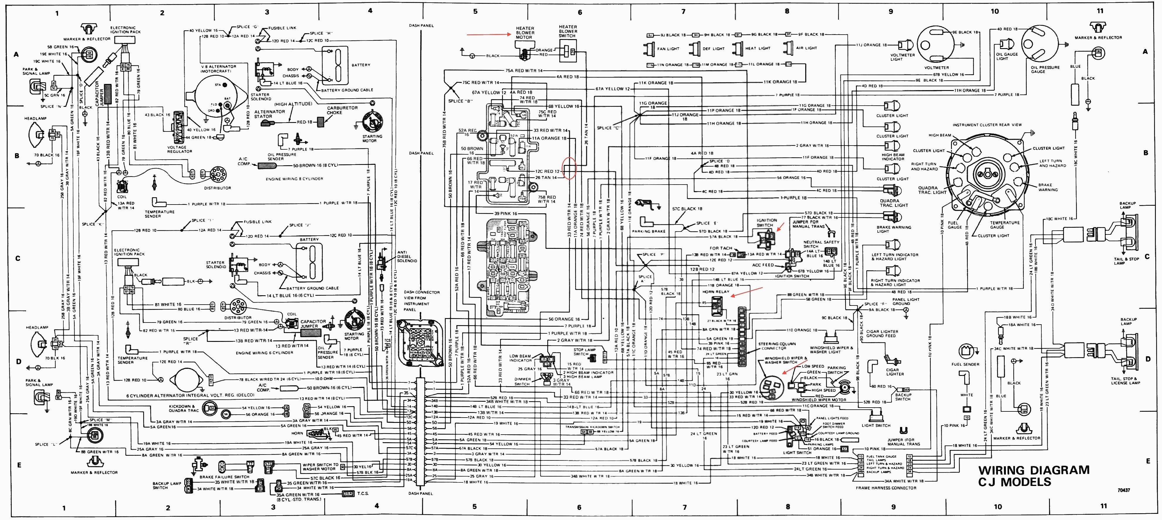
Instrument wiring diagram. All american 32006400 package guide rev 22713. Sn11 low volt light rev 71212. A wiring diagram is a streamlined standard pictorial depiction of an electric circuit. 1977 78 240 gauge assembly here s a diagram showing the pin outs for the 1977 78 240 instrument cluster. 01 six gauge set wiring diagram. Wiring harnesses are joined by using a multiple plug and receptacle connector block or a terminal post chassis junction block.
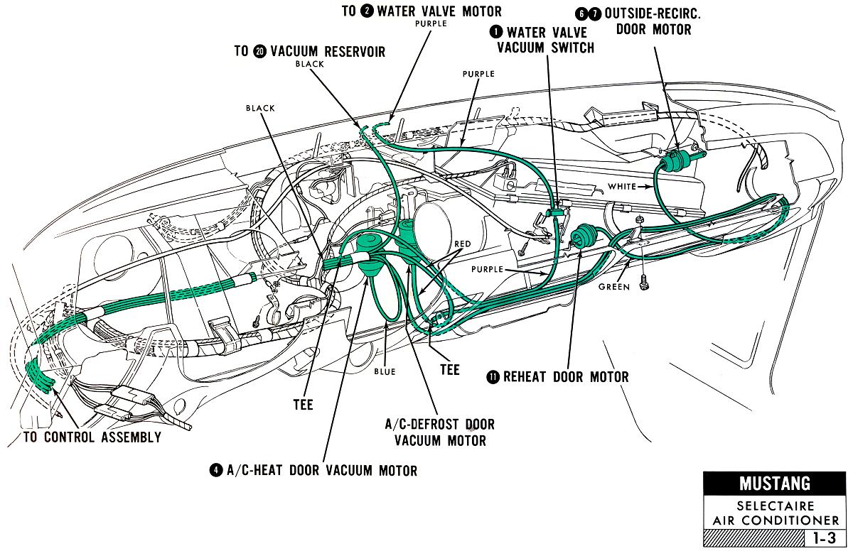
Download 6400 wiring instructions rev 2713. These types of diagrams are normally found with home appliances and automobile electrical systems figure 12. Six gauge set wiring diagram snwh03. Download sn11 low volt light wiring diagram 71212. These set of drawings are more detailed than process and instrument diagrams pids. A wiring diagram is a very simple way to show wiring connections in an easy to follow manner.
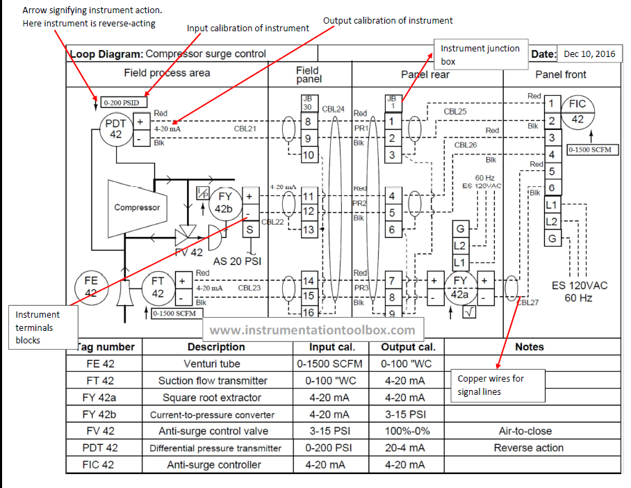
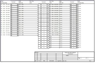
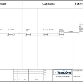
Loop drawings can be customized per customer taste although certain minimum standard information is required to be included in loop sheets. The next step is to get the power from the house battery up to the switch panel where we can use it to do some good. Wiring diagrams show the component parts in pictorial form and the components are identified by name. Instrument loop diagrams are also called instrument loop drawings or loop sheets. Loop diagrams are the most detailed form of diagrams for a control system and thus it must contain all details omitted by pfds and pids alike. Each harness or wire must be held securely in place by clips or other holding devices to prevent chafing of.
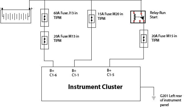
Most wiring diagrams also show the relative location of component parts and color coding of conductors or leads. This cluster uses a cable type speedometer. Basics of instrument loop diagrams. Two conductors a positive from the battery switch with a fuse and a negative from the ganged together battery negatives should be ran to where the central switch panel is. Some of the pins in these images are noted with pos or neg these notations refer to the circuit polarity going to the lamps related to those circuits. It shows the elements of the circuit as simplified shapes and also the power as well as signal links in between the gadgets.
The two most commonly used are the wiring diagram and the schematic diagram. In the instrument panel area plastic insulated blade type connectors and screw type terminals are used. They are wiring schematic and pictorial diagrams. Types of electrical diagrams or schematics. Download 3200 wiring instructions rev 2713. A wiring diagram generally provides details about the relative position and plan of gadgets and also terminals on the gadgets in order to help in building or servicing the device.
Gallery of Instrument Wiring Diagram