We have parts and diagrams available for evinrude johnson outboard wiring. Select a tachometer mounting location that is in full view of the operator.
Dc95 Johnson Outboard Tachometer Wiring Diagram Wiring
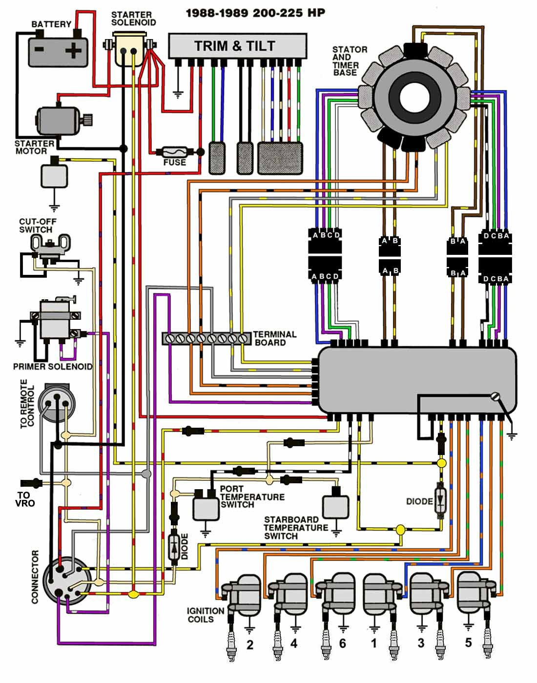
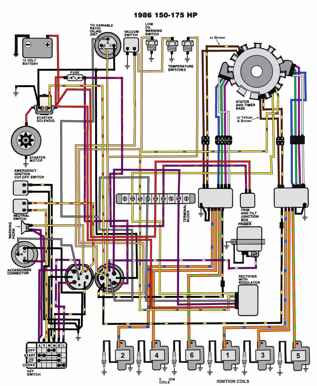
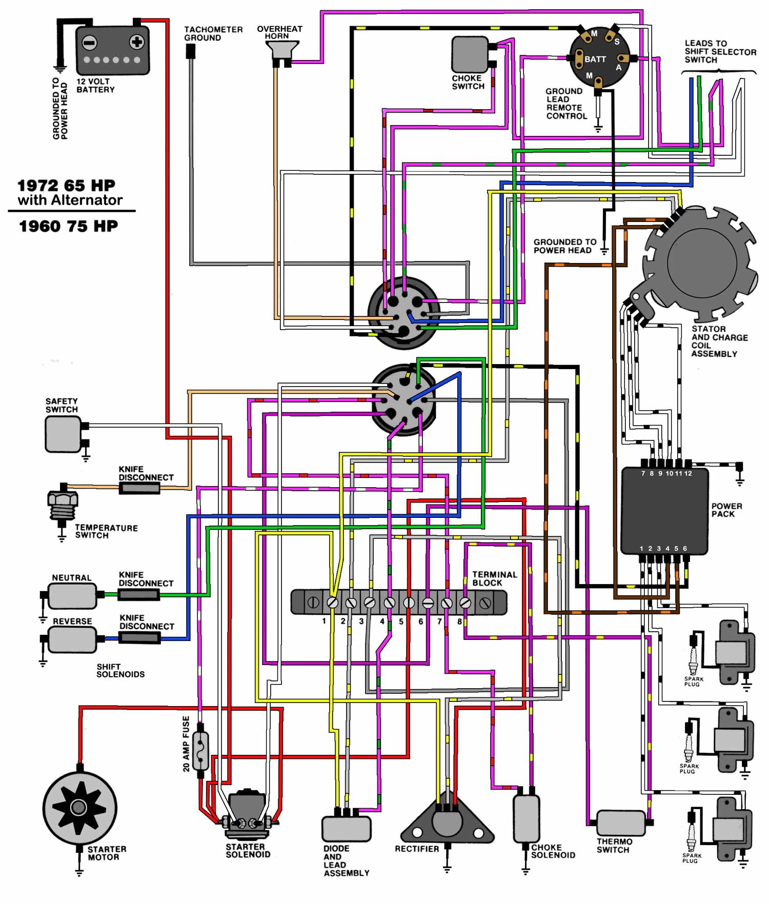
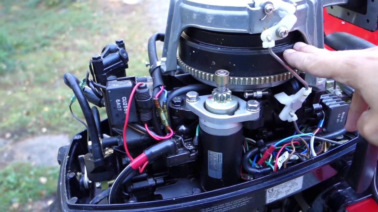
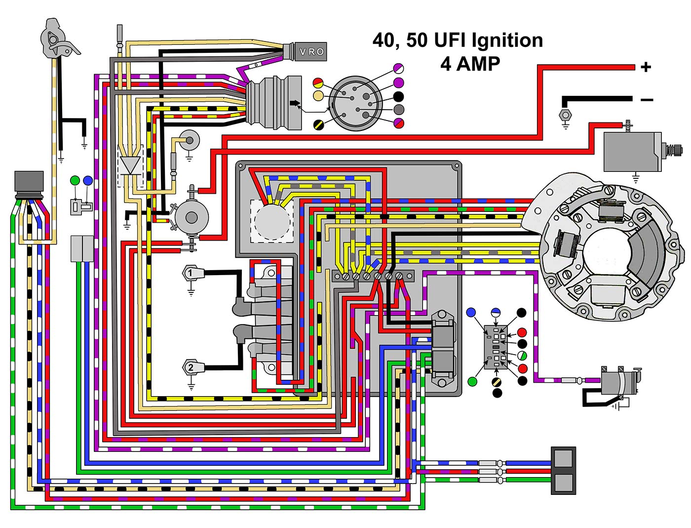
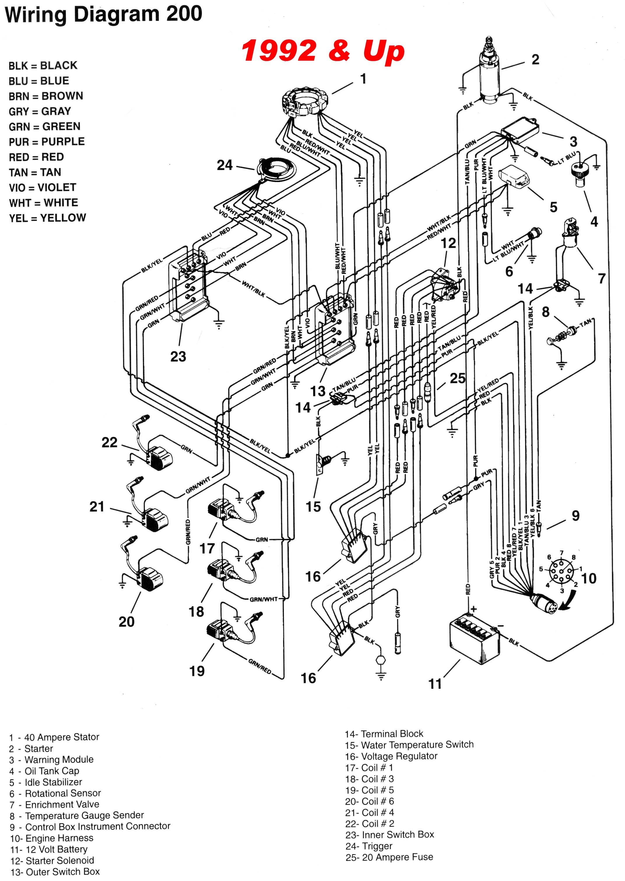
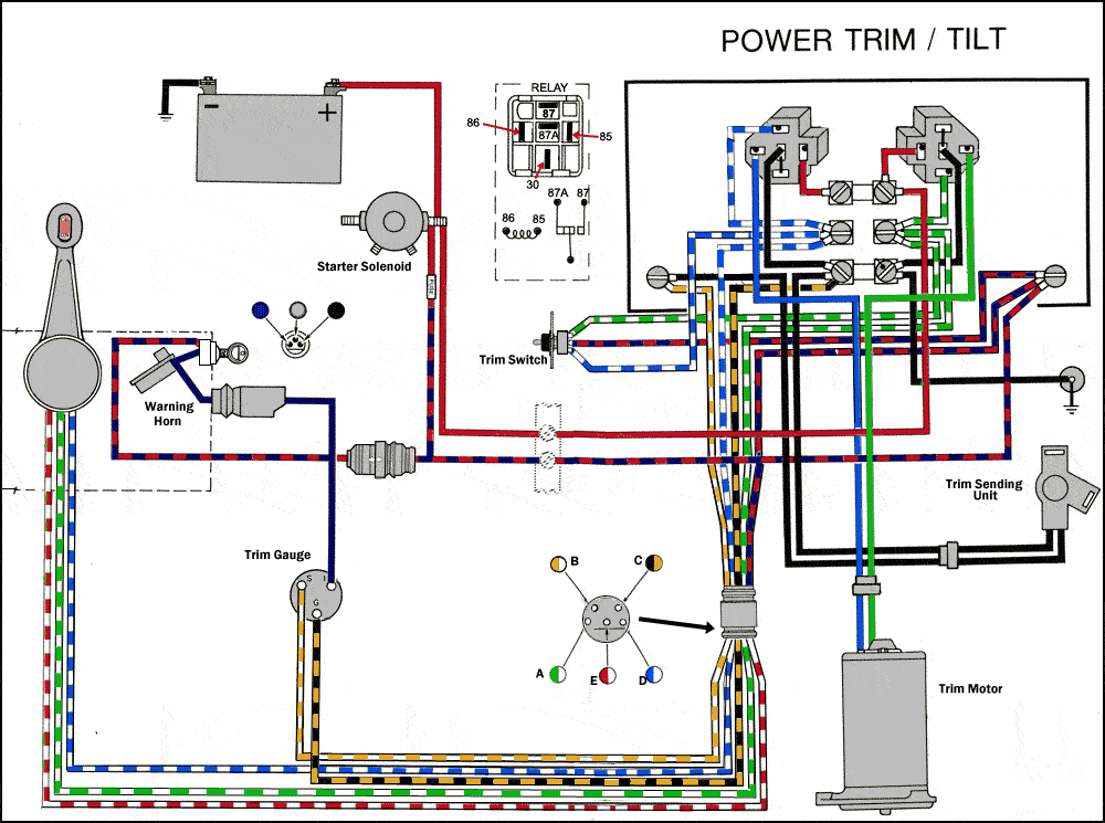
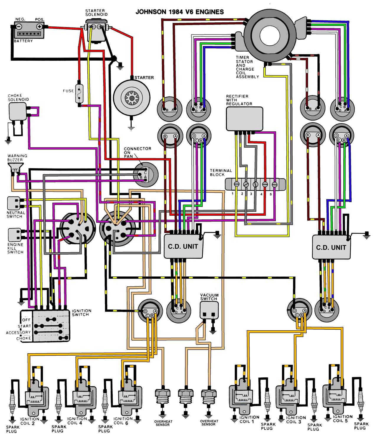
Johnson outboard tach wiring diagram. Outboard engine wiring series links. Here is a listing of common color codes for evinrude and johnson outboard motors. The wiring basics of connecting a tachometer rpm gauge to an outboard motor. Mount the tachometer so water will not collect on the face or drip on the case and wires. It shows the components of the circuit as streamlined forms and the power and also signal links in between the tools. Image result for 70 hp johnson wiring to tachometer etc diagram rh pinterest com 70 hp johnson outboard 8 wires wiring diagram i bought a used 70 hp johnson outboard for my boat and had remove the gray wire from the tachometer.
A wiring diagram is a simplified standard pictorial representation of an electrical circuit. Wondering where n ell to get great parts for your outboard. Drill a 3 38 in. Click picture if your mfgr. A fun old porcelain sign and ancient tools. T hat motors 7 years old.
Wiring diagram 35 force wiring hp johnson outboard wiring image result for 70 hp johnson wiring to tachometer etc. These codes apply to later model motors approximately early 80s to present evinrudejohnson common wiring color codes. Outboard motor control wiring part 1. Collection of johnson outboard ignition switch wiring diagram. If the tachometer is covered by a transparent shield the shield must be adequately ventilated to help prevent sunlight heat soak. 1996 evinrude 40hp parts used in this test.
86mm hole in the dashboard.
Gallery of Johnson Outboard Tach Wiring Diagram