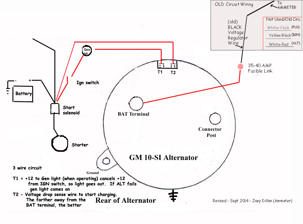
Many alternators require ignition voltage to initiate charging. 800 x 600 px source.

Pin By Tarek Sadat On Fav With Images Auto Body Work Vw
Kancil alternator wiring diagram. 1 wire alternator diagram carlplant size. The headlights dashboard lights radio and interior lights all rely on the alternator to keep the battery charged and the car operating. Collection of three wire alternator wiring diagram. The alternator charge wire routes direct to the battery and not through any switch connection the alternator will not operate correctly if not connected direct to battery or directly through the ammeter. Connect the output cable see cable sizing recommendations below ground field wire stator tach wire if needed and other necessary wiring. Some shimming or modification to the alternator mount may be required to assure proper alignment.
You must verify that all required connections are connected to the proper terminal and have the correct voltage in order for the alternator to operate properly. Connect alternator to balmar regulator wiring harness as indicated in wiring diagram included on page 12. The wiring that comes with our kits should be used as it is sized to handle the amperage. Right here are some of the leading drawings we get from various sources we wish these pictures will work to you and also ideally extremely appropriate to what you want about the 1 wire alternator wiring diagram is. With key on power is then transferred through the no charge indicator light to the 1 spade on the alternator regulator connection. An alternator works with the battery to supply electricity to components of a vehicle.
If you are able to look at a manufacturers diagram of the alternators connectors the wire that slides over pin 1 of the alternator leads to the positive connection on the vehicles battery and senses voltage. Below you will find the most common alternator circuits used on marine applications. If the voltage rises above or falls below 12 volts the alternators internal voltage increases or reduces power output to. The alternator has a rotor that spins when the engine cranks. Ford alternator wiring diagram this is the diagram of every components in the alternator. How do i wire my marine alternator.
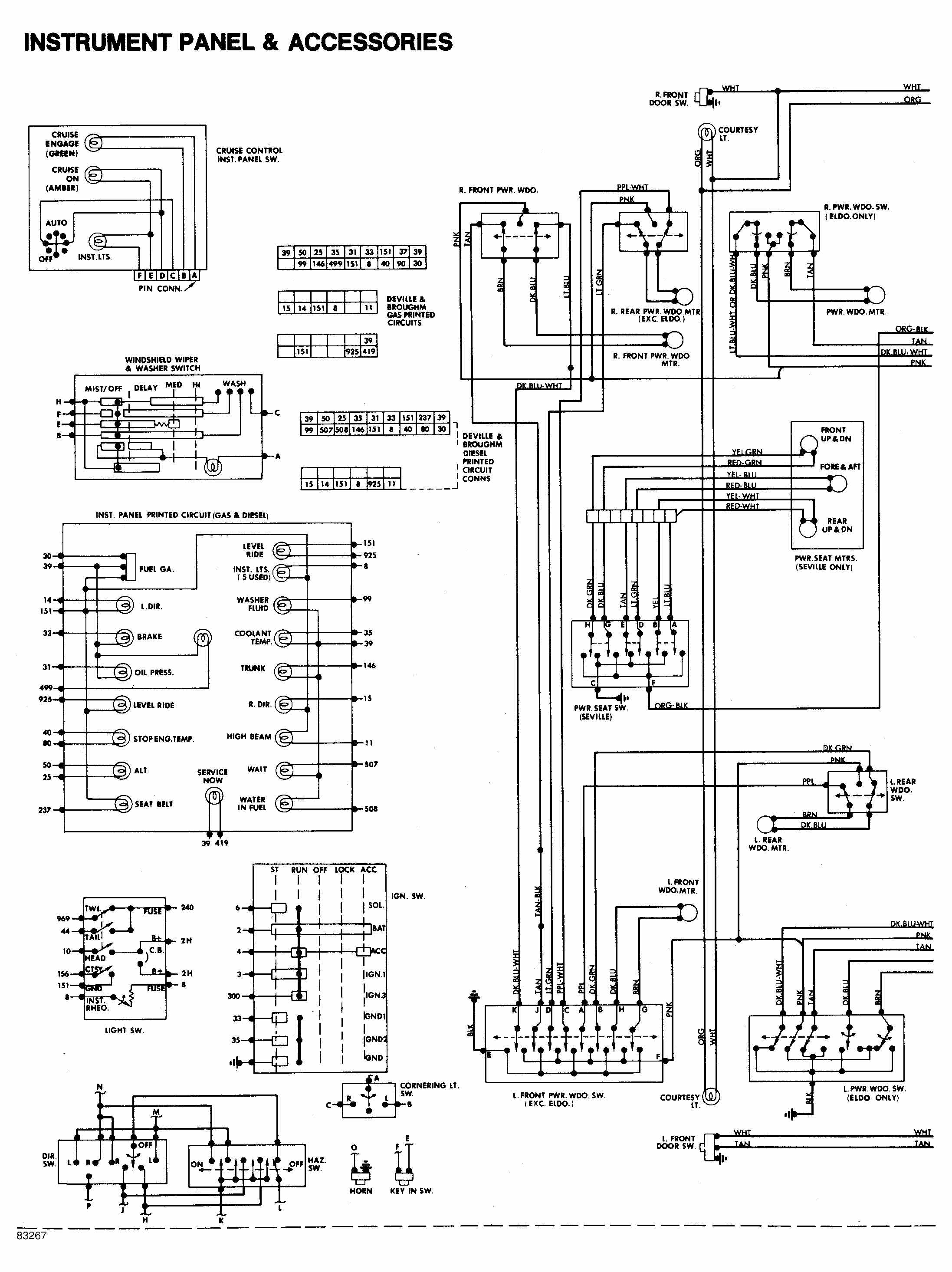
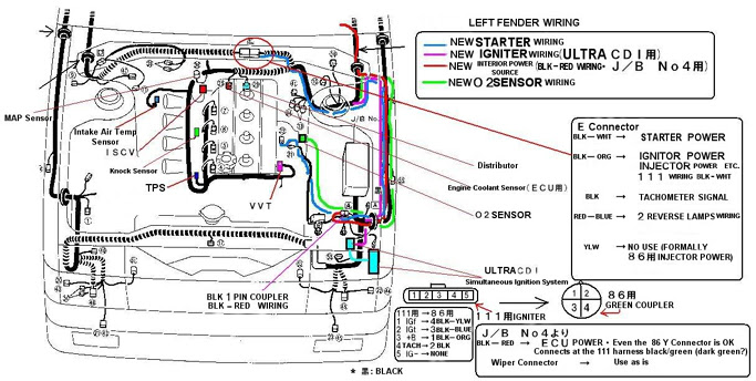
It is a diagram for the alternator in a ford focus see also ford focus repair manual ford escort ford f 100 ford taurus ford mustang ford model t ford gt40 ford thunderbird ford shelby cobra and other ford cars that use the similar alternator. A wiring diagram is a simplified traditional pictorial depiction of an electric circuit. This diagram shows the simple wiring diagram for negative ground delco si series alternators the ignition switch is most commonly powered from the starter battery stud but source may vary depending on application. This rotor spins past wire coils causing a magnetic field. It shows the parts of the circuit as streamlined forms and also the power as well as signal links in between the gadgets. Wiring harness configuration diagrams connector symbol 01 thru a 50 earth cable c 4 wiring harness configuration diagrams engine compartment a 01 2 b brake fluid level switch a 03 1 b noise condenser a 04 1 alternator a 05 4 gr alternator a 09 1 b starter a 10 1 starter a 12 2 b fuel pressure solenoid valve a 16 4 b.
Gallery of Kancil Alternator Wiring Diagram