Kfd2 stc4 ex1 hazardous area 4 20 ma product info. 151 figure 923 isolated transmitter power supply this figure shows a galvanically isolated transmitter power supply similar to figure 923 except the safe area output sinks hazardous area.

Gr40 Smt16b 125lac2885 深圳市华联欧国际贸易有限公司手机版
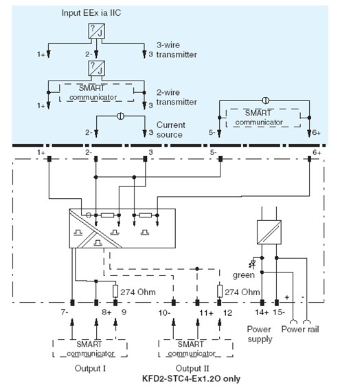
Kfd2 stc4 ex1 wiring diagram. Release date 2014 12 01 1623 date of issue 2014 12 01 122581engxml technical data kfd2 stc4 ex12o 2 refer to general notes relating to pepperlfuchs product information. Div 1 2 zone 0 1 2 powerrailconnection safeareadiv. K duct bu upr 03 profile rail with upr 03 insert 3 conductors wiring comb field side blue kfd2 stc4 ex1 y1 release date. An internal resistor at terminal 9 is. 2020 04 06 date of issue. 15 14 9 3 1 6 2 5 1 3 3 3 2 1 2 7 8 4 20ma hazardousarea kfd2 stc4 ex1 5 6 kfd2 stc4 ex1 engineers guide page 7 accessories page 443 power supplies page 401 surge suppression page 413 lastest info.
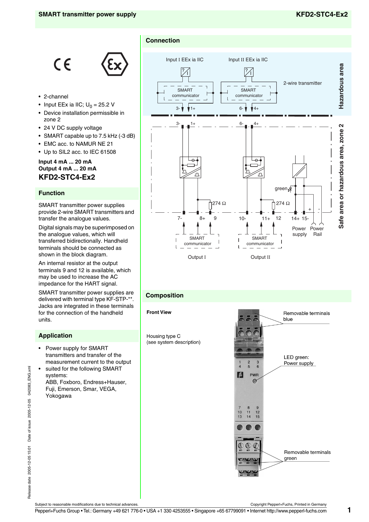
Kfd2 stc4 ex1 smart transmitter power supplies provide a 2 or 3 wire smart transmitter and transfer the analogue values. Kfd2 stc4 ex12o pwr front view led green. It transfers the analog input signal to the safe area as an isolated current value. This isolated barrier is used for intrinsic safety applications. Digital signals may be superimposed on the analogue values which will transferred bidirectionally. Handheld terminals should be connected as shown in the block diagram.
The device supplies 2 wire and 3 wire smart transmitters in a hazardous area and can also be used with 2 wire smart current sources. 283680engpdf pepperlfuchs group germany. 1 330 486 0002 singapore. Power supply removable terminals green removable terminals blue 3. 49 621 776 2222 4 refer to general notes relating to pepperlfuchs product information.
Gallery of Kfd2 Stc4 Ex1 Wiring Diagram


__37942.1571960310.jpg?c=2)