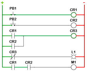
1a ladder diagram translates similarly to a book. The loads in a ladder diagram are always and shall be connected in parallel on the rungs.
Circuit Diagram Ladder Logic Open Loop Controller Wiring
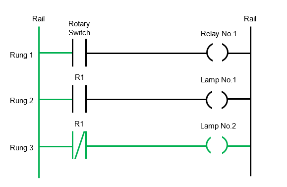
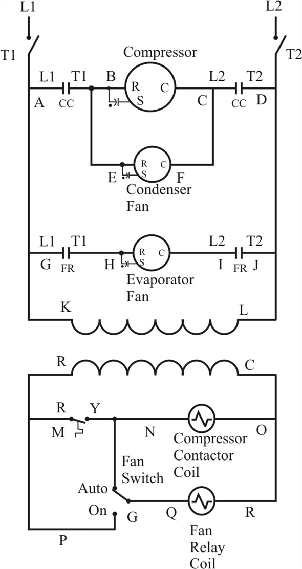
Ladder wiring diagram. It does not show the actual locations of the components. Ladder diagrams sometimes called ladder logic are a type of electrical notation and symbology frequently used to illustrate how electromechanical switches and relays are interconnected. Usually drawn like a ladder hence the name ladder diagram. In drawing a ladder diagram certain seven conventions are adopted. The power flow is taken to be from the left hand vertical across a rung. Read the ladder diagram from left to right then up to down in order.
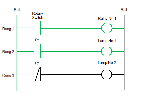
The control circuit voltage is usually rated at 12v 120v depending on the rated values of the loads connected in the circuit. Convention 2 each rung on the ladder defines one operation in the control process. A ladder or line diagram is a diagram that shows the function of an electrical circuit using electrical symbols. Therailsare the two dark vertical lines that represent the power source to the control circuit. Ladder diagrams allow a person to understand and troubleshoot a circuit quickly. The load is the last component connected to the right side of the rail unless.
The ladder diagram shown in figure 4 is easy to read since there are only two basic parts the rails and the rungs. The two vertical lines are called rails and attach to opposite poles of a power supply usually 120 volts ac. Convention 1 the vertical lines of the diagram represent the power rails between which circuits are connected.
Gallery of Ladder Wiring Diagram