Monday friday 8am 430pm 44 0115 949 7211. Ill muddle through but a diagram would speed things up a lot.

Series 2a Amp 3 Ignition Switch Wiring Series Forum Lr4x4
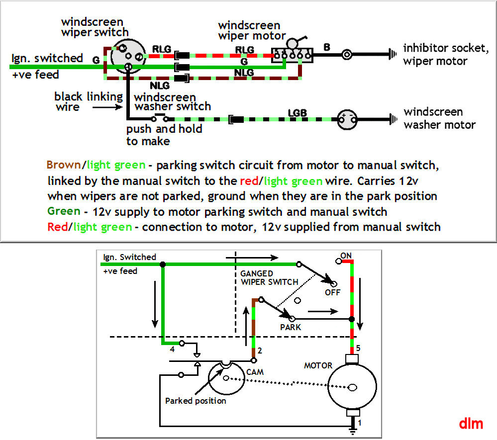
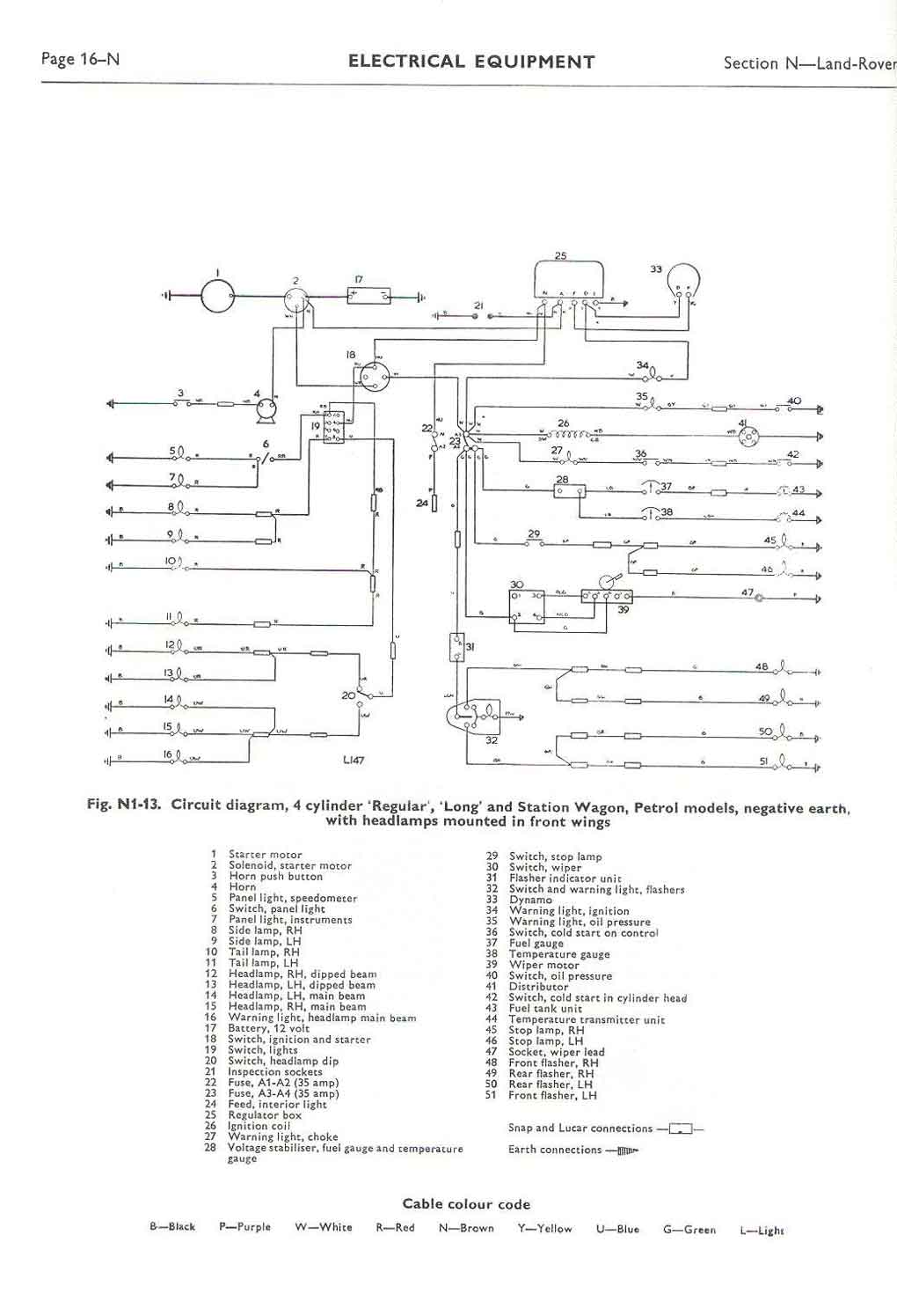
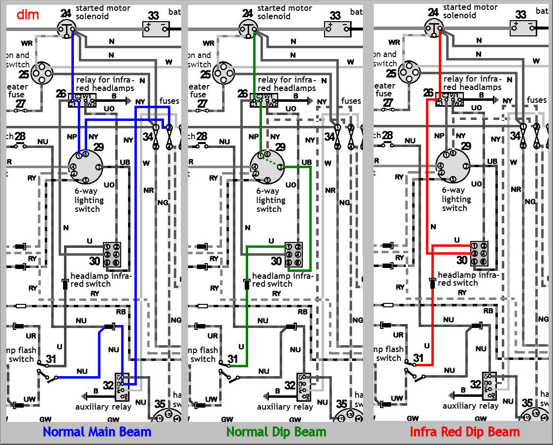
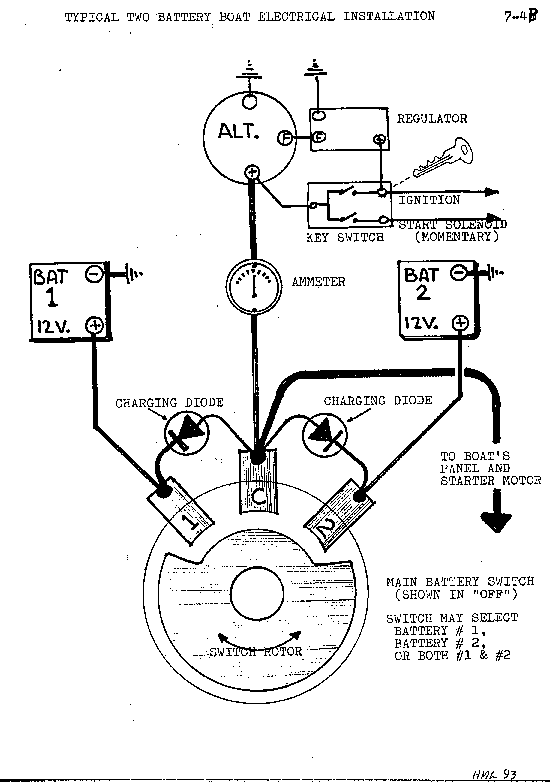
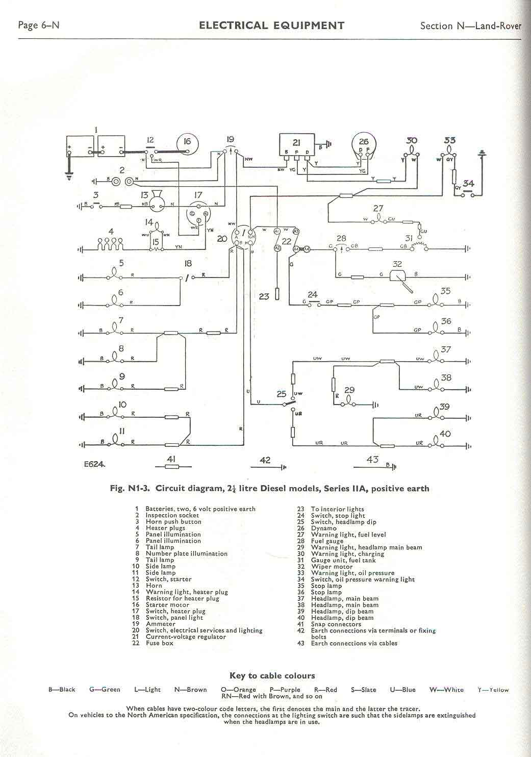
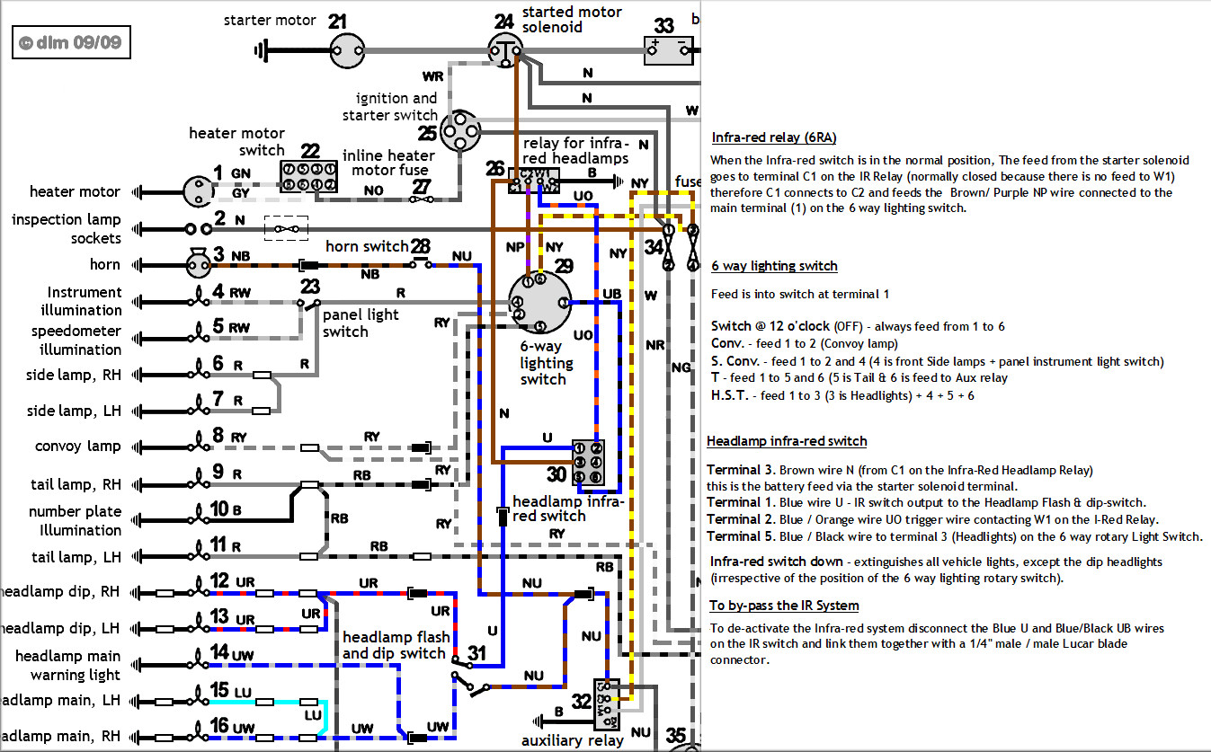
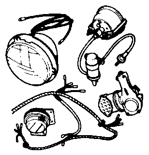
Land rover series 3 wiring diagram. Circuit diagram 24 volt models 90 amp generator with transistorised charging system. 34 mb manual series 1 land rover 15 mb sankey trailer 09 mb x panda cab land rover series camper 07 mb parts and accessories for land rover bearmach catalogue 220 mb defender fast parts 13 mb britpart catalogue 118 mb useful instructions for diy repair jobs fitting a canvas hood to series land rover 09 mb. Browse through the interactive land rover series 3 electrical diagrams to find parts for starting and charging ignition lights instruments wipers washers harnesses looms. Series 3 wiring diagram version 2. Circuit diagram 24 volt models 90 amp generator. Land rover series 3 wiring manual free download as pdf file pdf text file txt or read online for free.
I am rewiring mine with a harness taken from a 1983 diesel and the genuine workshop manual does not have a diagram of this part of the electrics at all. 551508 which is labeled up as bat ign st acc. Series 3 tools lr workshop this site aims to become the defacto source of information on land rover parts by being more accessible than microcat more unbiased than the retailers better curated than the forums and more accurate than all of them. Most series 3 wiring diagrams are in archive and available however there appear to be at least three distinct wiring configurations. Below are the documents. I have added some newer standard codes for accessories that might be added to a series land rover such as rear fog lamps a rear window wiper and washer driving lamps radio and electric fan.
Does anybody have a wiring diagram of the hazard flasher system on a series 3. Autosparks limited 80 88 derby road sandiacre nottingham ng10 5hu. Just would like some clarification on the wiring up of the ignition switch i have for my motor. Series 3 wiring diagram version 1. Series iii diagrams contributed by lee jones. Circuit diagram 34 ton 109 24 volt lr selenoid operated fuel cut off valve.
In general solid colours go from the power source to a switch and a stripped wire goes from the switch to the switched electrical component. The switch is a standard landy series 2a 3 petrol ignition switch and keys part no. Series 3 wiring standardisation emei g307 13. Where as i have a diagram showing connections.
Gallery of Land Rover Series 3 Wiring Diagram