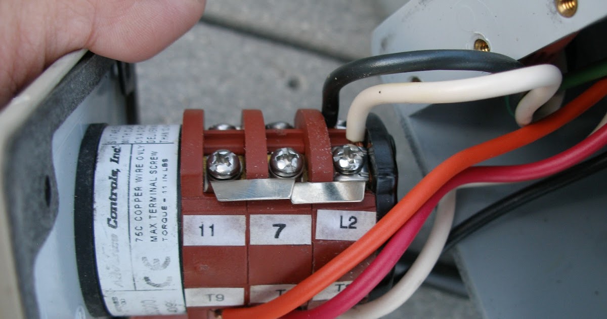
Gem black gem red gem orange t86 t5j10 gem white t1p1 t3 t2 t4 from motor windings to change motor direction switch t5 t8 motor wires. It shows the components of the circuit as streamlined shapes and also the power and also signal connections in between the devices.
Bremas Boat Lift Switch Chilangomadrid Com
Leeson boat lift motor wiring diagram. Electric motor wiring diagrams drum switch gfci boat hoist usa assumes no responsibility or liability for installations andor improper use of the equipment. Connect switch black with motor wire terminal 1 and terminal 3 with wire nut. Totally enclosed non venting housing tenv motor helps prevent dirt and insects from getting into the motor. This housing improves the life of the motor. Wire inside the motor. If not the arrangement will not function as it ought to be.
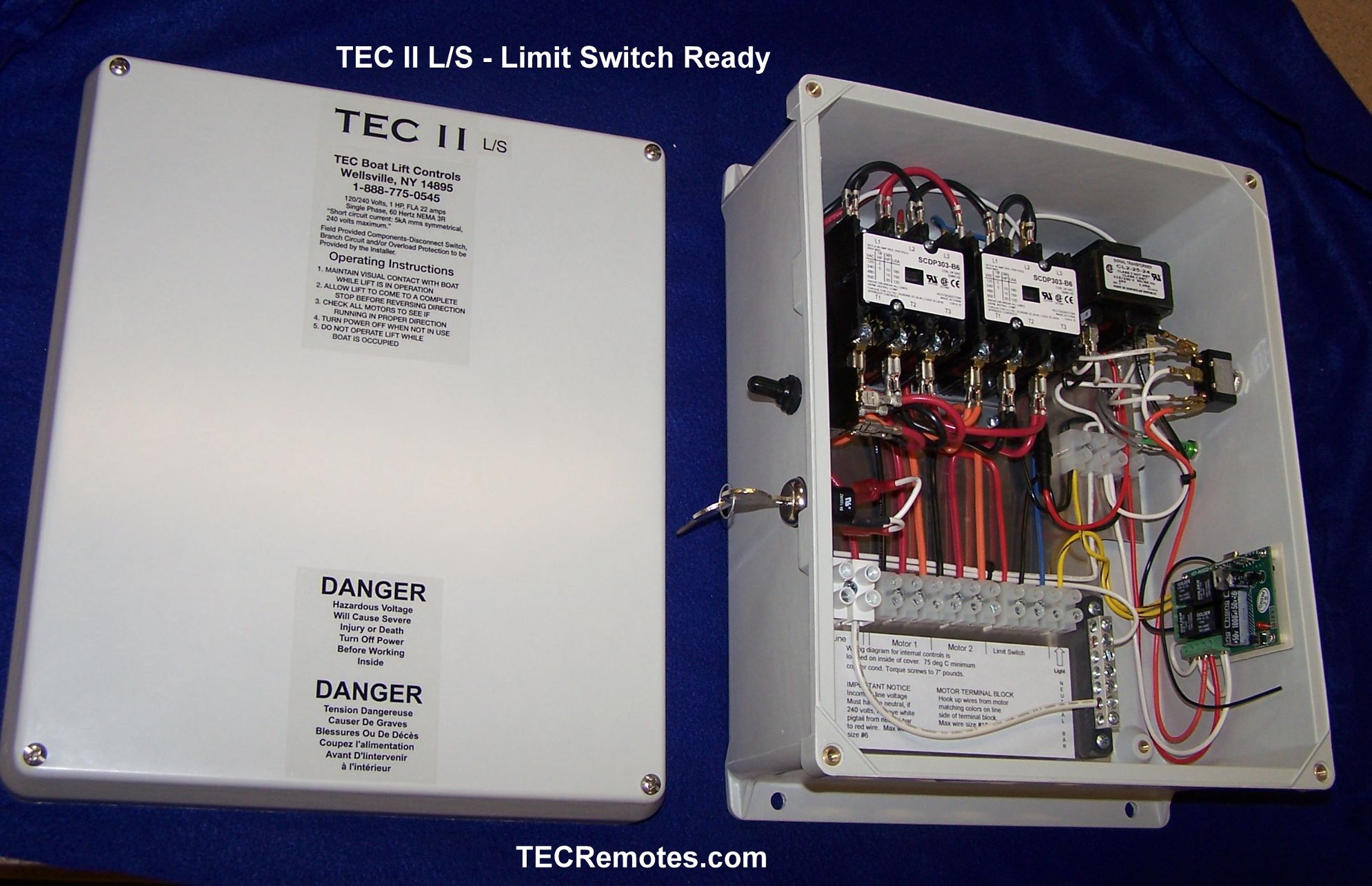
Leesonelectra gear c face frame boat lift motor 110v wiring instructions with bremas switch and gfci. Remote wiring standard t or wires wired at 120 vac. Connect switch red with motor wire terminal 5 with wire nut. Red saiitci i ground or. Connect switch orange with motor wire terminal 2 and terminal 4 with wire nut. These same instructions apply to any 13hp 12hp or 1hp.
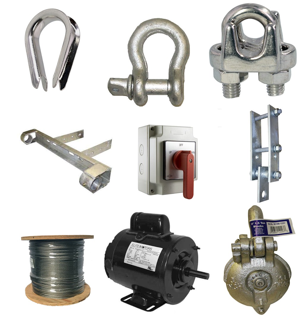
Boat hoist usa is not responsible for the design construction or installation of docks piers or lifts. A wiring diagram is a streamlined standard pictorial depiction of an electric circuit. Standard duty single phase motor with a start capacitor. Nema ul listed and csa approved they are standard duty single phase capacitor start 56 frame motors compatible with most flat plate belt driven hoists. Check operation of motor. T a lee son motor 115 vac.
This guide is intended to be used as a reference and a general guideline only. The leeson 34 hp painted boat lift motor is a nema motor that is ul listed and csa approved. Aluminum boatlifts boat lift motors hoist jetski lifts electrogear leeson fix boat lift u s leeson motors 1 hp 56 frame boat lift motor 110v wiring leeson electric. Leeson 34 hp painted boat lift motor. Leeson motor wiring diagram leeson 1hp motor wiring diagram leeson 3 phase motor wiring diagram leeson 5hp motor wiring diagram every electric structure is made up of various distinct components. Each part should be placed and connected with other parts in specific way.
Connect switch white with motor wire terminal 8 with wire nut. Cap gem white wire not used. Leeson electrogear fix marine to change from 120 to 240vac. With the help of frank from franks motor shop it is shown how to easily safely and quickly to wire a 34hp electric motor in this video. Put cover on motor. Collection of leeson electric motor wiring diagram.
Connect switch ground green to motor ground nut using grounding screw. 2attach 3 motor. The leeson boat lift motor has a totally enclosed non vented housing tenv to prevent dirt and insects from entering.
Gallery of Leeson Boat Lift Motor Wiring Diagram