In a dlm local network with only lmrc 222 room controllers the lmrc 222 with the highest serial number is the master carrying load 1 and load 2. The dimming curve must be set for proper operation.

Specs Vol 2 A Pleasant Construction
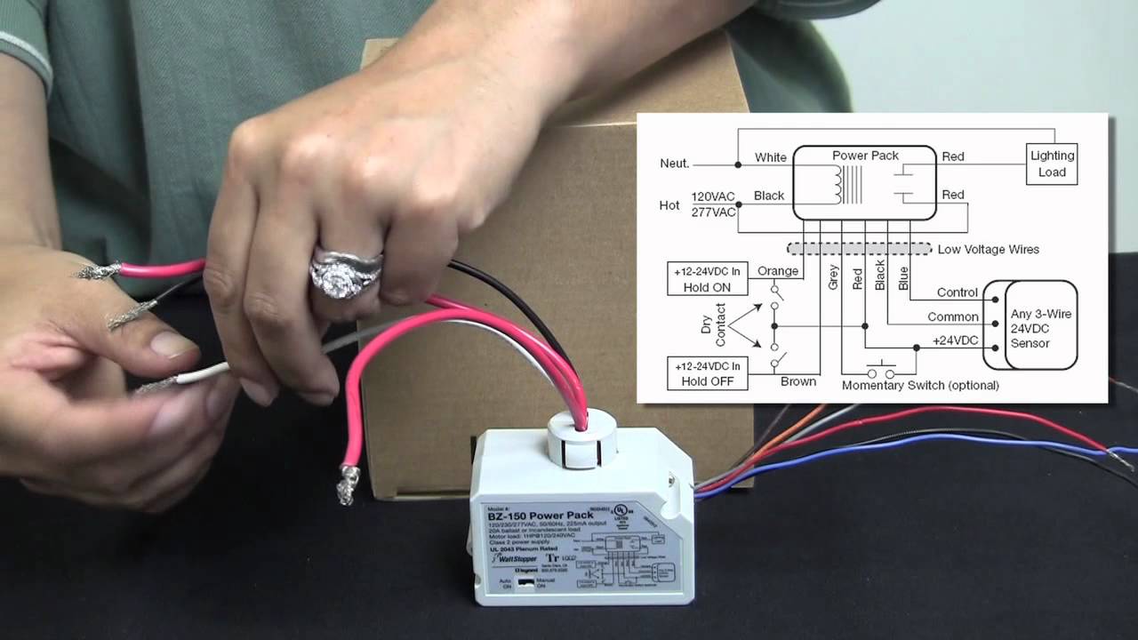
Lmrc 212 wiring diagram. The lmrc 211 347 is rated for up to 15a. For dimming ballasts or drivers connect the 0 10v control wires to the 0 10v terminals that match the load relay output connection. 90 133 lmrc 212 two relay wiring diagram pdf 5681kb 90 133 lmrc 212 two relay wiring diagram dxf 55079kb. Lmrc 212 and the lmrc 212 347 room controllers each have two load relays. The success of a dlm network installation and the functionality of the segment to this device is followed exactly as depicted in the wiring instructions and diagram. 12 typical wiring diagrams tw drawings provide wiring diagrams for dlm room controllers relays and.
25082018 25082018 1 comments on wattstopper lmrc 212 wiring diagram. Total load for lmrc 213 not to exceed 20a. All line voltage wiring is 12 awg. Lmrc 222 75 c copper wire only santa clara ca 8008798585 industrial control equipment 46a9 indoor use only mounting the controller the room controller mounts to a four square deep junction box using the included mounting plate with the hinge pins extending away from the box as shown. The lmrc 211 is rated for up to 20a. Wattstopper lmrc 212 wiring diagram.
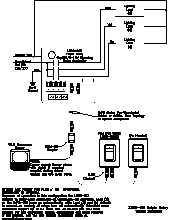
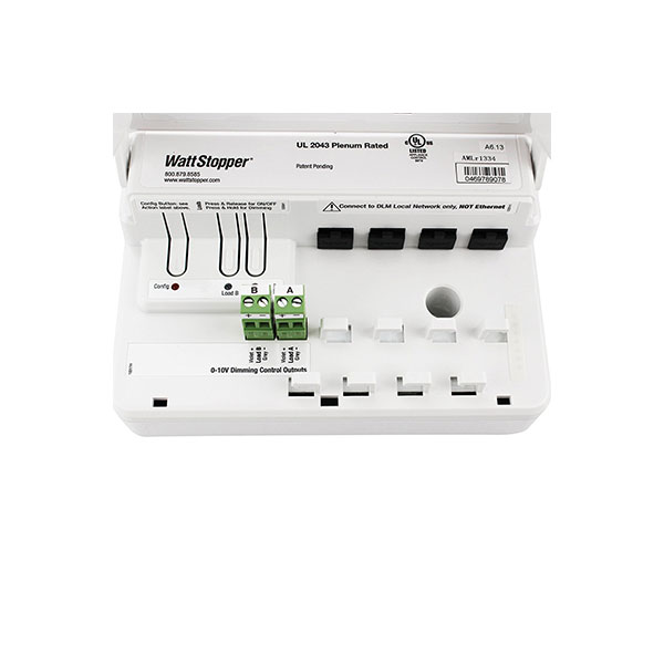
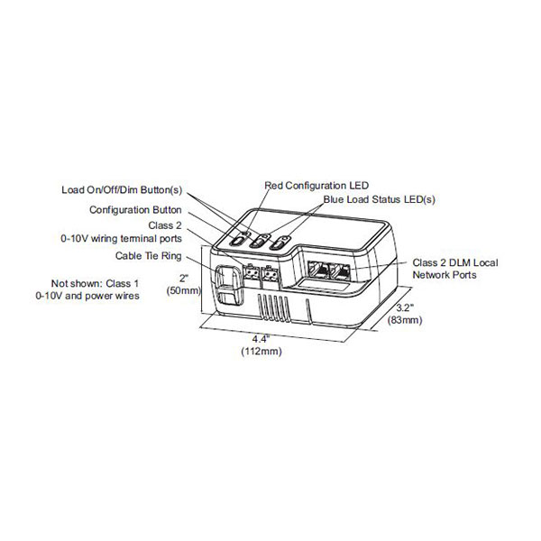
Connections shown are for example only. Class 1 0 10v and power wires configuration button class 2 0 10v wiring terminal ports cable tie ring lmrc 112 line voltage. In a dlm local network with only lmrc 212 or lmrc 212 347 room controllers the room controller with the highest serial number is the master carrying load 1 and load 2. Controls lmrc eliminating wiring errors wattstopper dlm local network parameters lmrc digital onoff volt dimming room controller with 2 relays and 2. The wattstopper digital lighting management local network dlm. Lmrc 221 75 c copper wire only santa clara ca 8008798585 industrial control equipment 46a9 indoor use only mounting the controller the room controller mounts to a four square deep junction box using the included mounting plate with the hinge pins extending away from the box as shown.
All line voltage wiring is 12 awg. The lmrc 213 communicates to all other dlm devices connected to the dlm local network. Terminate wiring according to wiring diagram. The next highest serial number would have load 3 and load 4 and so forth. The lmrc 222 has two load outputs. Each relay is rated for up to 20a.
The low voltage lmrj cables can connect to any dlm device with an open rj45 receptacle. Terminate wiring according to wiring diagram. The next highest serial number would have load 3 and load 4 and so forth. Do not connect different load types to the relay. Sample connection diagram with class 1 class 2 dimming control wiring 44 112mm 32 83mm 2 50mm load onoffdim buttons red configuration led blue load status leds class 2 dlm local network ports not shown.
Gallery of Lmrc 212 Wiring Diagram