When a tap inside your home is turned on there is a subsequent flow of water. These set of drawings are more detailed than process and instrument diagrams pids.

File Cmf Scr Loop Schematic Png Wikimedia Commons
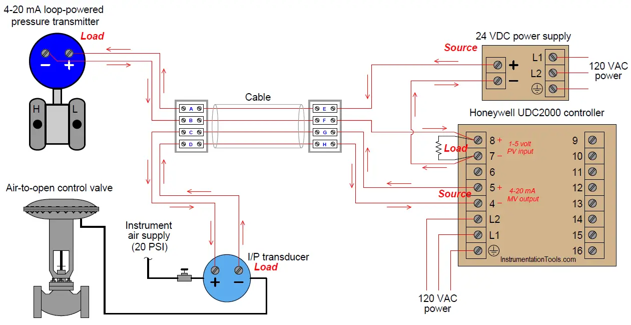
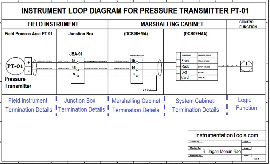
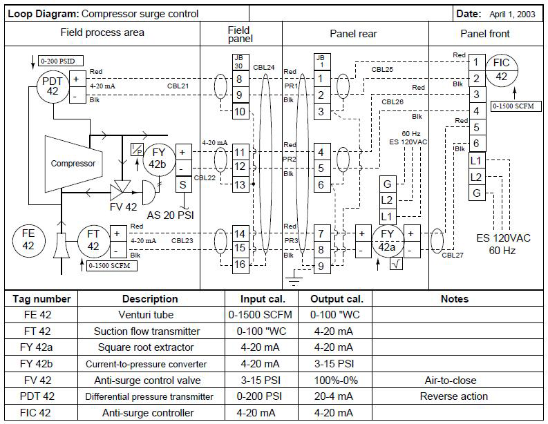
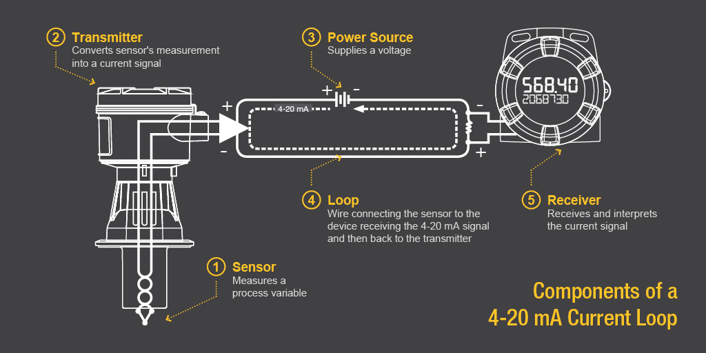
Loop wiring diagram for flow control loop. The signal travels through a wire loop to a receiver and the receiver displays or performs an action with that signal. This diagram illustrates wiring for one switch to control 2 or more lights. Wiring diagram of loop powered isolator with external powered 4 wire transmitter. This would be a short circuit and would prevent the train from getting power. The flow of water is analogous to the flow of electrons or current. Instrument loop diagrams are also called instrument loop drawings or loop sheets.
Multiple light wiring diagram. Pids and loop diagrams pids and loop diagrams are construction and documentation drawings that depict the flow of the process and illustrate the instrumentation control and measurement interactions wiring and connections to the process. To the novice it may seem excessive to include such trivia as wire colors in a loop diagram. The diagram below shows a typical flow control loop. Thus the loop diagram is the most detailed form of diagram for a control system as a whole and as such it must contain all details omitted by pfds and pids alike. The following is seven wiring diagrams of the loop powered signal isolator and the various powered sensors and the different types of control system input module or input of instrument.
A loop is made from a continuous run of wire with no splices which is typically wound in a rectangular shape and saw cut into the existing. The source is at sw1 and 2 wire cable runs from there to the fixtures. The process is illustrated in sections or subsystems of the process called loops. Loops are used to stop or reverse a moving gate to allow free exit from or entrance to a site or as an arming loop to allow entrance with the use of a transmitter or some other access control device. The wiring method of the external powered transmitter. The hot and neutral terminals on each fixture are spliced with a pigtail to the circuit wires which then continue on to the next light.
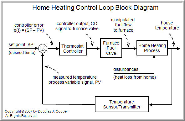
Loop powered devices are often much lower cost than other process control devices with built in high power electronics. A loop diagram will detail the connections of. This is simply because the expensive components that could be included in these devices such as power supplies mechanical relays or advanced digital or analog signal output components are omitted in order to limit the amount of power necessary to operate the device. 5 the control valvefcv that either opens or close based on the signal from the controller to either open or close to increase or decrease flow. Loop diagrams are the most detailed form of diagrams for a control system and thus it must contain all details omitted by pfds and pids alike. The insulated rail joints are necessary because without them electricity would flow from one side of the power pack around the loop and directly back to the other side of the power pack.
The 4 20 ma current loop is the prevailing process control signal in. The first diagram shows a train green arrow entering a two rail reverse loop.
Gallery of Loop Wiring Diagram For Flow Control Loop