100 of gas in the tank green 7 onoff button changes the tech controller working mode. Led switchboard chart 1 gas on indicator blue 2 gas reserves indicator red 3 app.

Hyster Forklift Manuals Library Download The Hyster Pdf
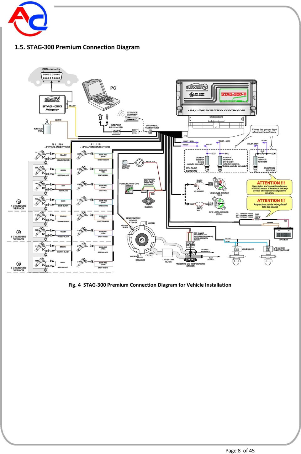
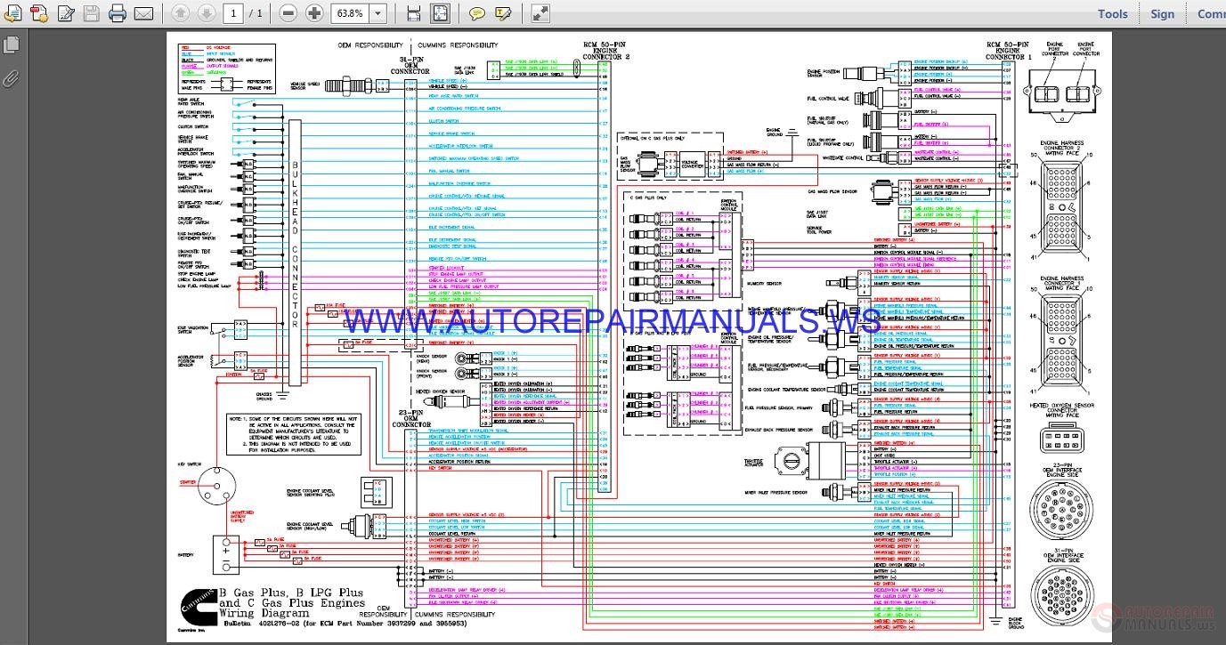
Lpg wiring diagram pdf. Lpg wiring diagram pdfelectrical wiring diagram for lighter 2001 sequoia 1967 chevy pickup wiring diagram schematic 1988 chevy k1500 wiring diagram chevy impala radio wiring diagram 2012 silverado radio wiring 1997 toyota camry fuse box map 2011 m37x infiniti fuse box majestic car radio wiring diagram 5qwghsteinig fotografiede. Tech lpg controller installation manual and controller programming manual figure 1. Do not allow lpg to accu mulate in areas below ground level such as in a service pit or under ground ventilation systems. The components has to be installed as shown in the wiring diagram sequential injection unit powerjet plus pic. Feed the lpg system and check carefully for any gas leakage using soap water or a gas detector. This control has to be done in any junction of the lpg line both high.
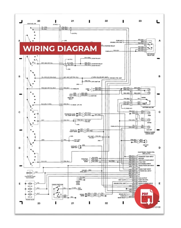
75 of gas in the tank green 6 app. 50 of gas in the tank green 5 app. It shows the components of the circuit as simplified shapes and the faculty and signal contacts in the middle of the devices. Lpg wiring diagram pdf. Lpg wiring diagram pdf wiring diagram is a simplified conventional pictorial representation of an electrical circuit. 060208 1 in pl.
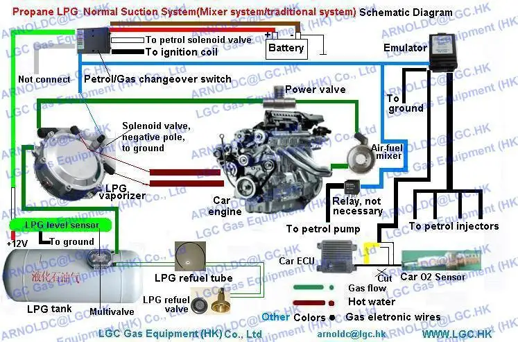
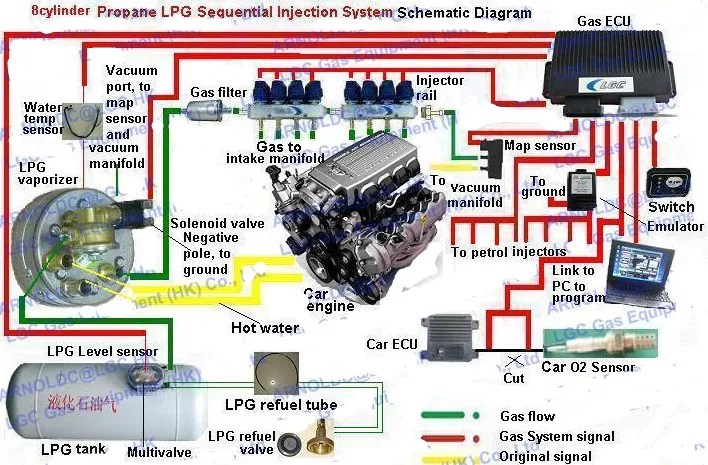
Lpg is stored in the fuel tank as a liquid. Lpg sequent plugdrive general wiring diagram only the white wire or both yellow and yellowblack wires must be connected to the eobd diagnostic connector and not together at the same time europa 2 multivalve genius mb reducer water temperature sensor lpg solenoid valve. 25 of gas in the tank green 4 app. 7 fix the electronic unit to the body inside the hood. When lpg contacts the atmosphere it immediately expands into a gas resulting in a refrigeration effect that can cause severe burns to the skin.
Gallery of Lpg Wiring Diagram Pdf