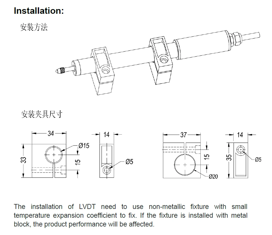
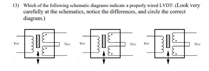
Lvdts operate on the principle of a transformer. Here the core is protected by the thing whose location is being calculated while the coil assembly is increased to a stationary structure.
Measuring Position And Displacement With Lvdts National
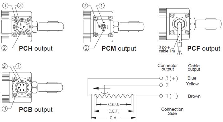
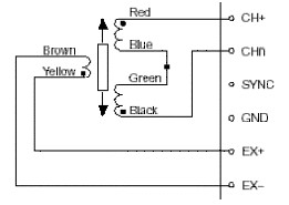
Lvdt wiring diagram. The purpose of this document is to provide the steps to configure anecessary lvdt module that n measures the position of an lvdt transducer in four wire mode configuration. A wiring diagram is a streamlined traditional photographic representation of an electric circuit. Lvdt four wire mode setup procedure. Wiring diagram pictures detail. There are lot of latest projects in electronics and communication. It reveals the elements of the circuit as simplified shapes as well as the power and also signal links between the tools.
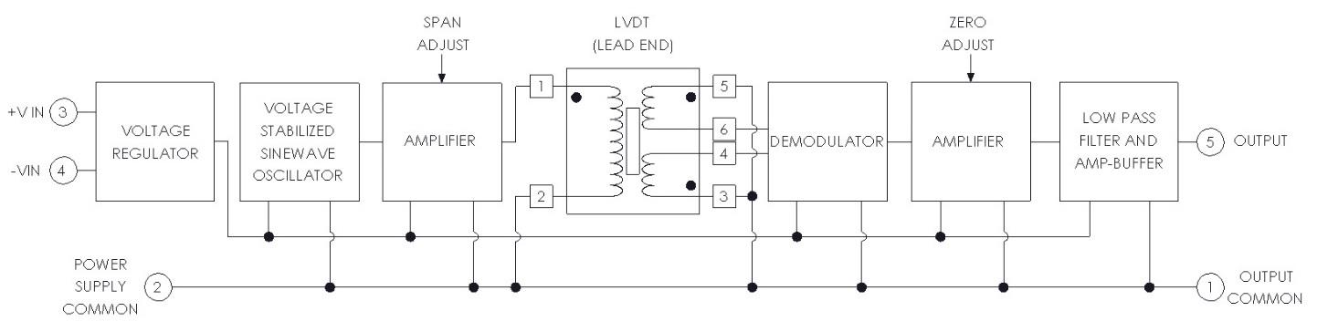
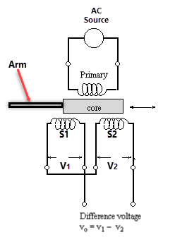
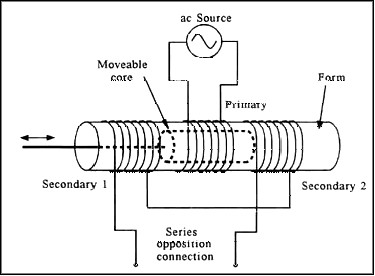
Ad589 integrated circuit provides a complete signal conditioner. The coil assembly is typically mounted to a stationary form while the core is secured to the object whose position is being measured. As shown in figure 2 an lvdt consists of a coil assembly and a core. Excitation voltage 3vrms excitation frequency 400hz channel one is used in the lvdt module. In this link you will also get the source code electronics circuits circuit diagram with every project. In the wider groove the o ring is supported by two backup rings to avoid any o ring extrusion due to fluid pressure.
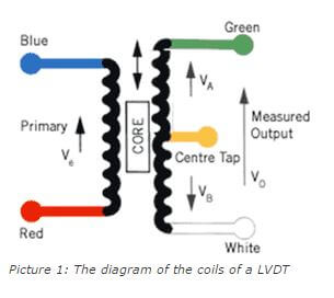
The coil assembly includes three wire wound coils on the hollow shape. 2 082016 page 1 introduction and purpose the lvdt linear variable differential transformer is an absolute positiondisplacement transducer that converts a distance from a mechanical reference zero or null position into a proportional electrical signal containing phase for direction and. Literally a circuit is the course that enables electrical power to circulation. The 24awg mil w 2275933 24 lead wires should be routed. Lvdt wiring diagram because the magnetic field tends to run along the core and spread out at the ends the flux linkage between the center coil and the end coils depends on the. The above lvdt sensor diagram comprises a core as well as a coil assembly.
Sensor solutions lvdt principles of operation rev. Getting from factor a to point b. Linear variable differential transformers lvdt are used to measure displacement. Lvdt linear voltage differential transformer is widely used as linear position sensor. A typical thread mount lvdt with flying leads is shown in figures 3 and 4. Lvdt wiring diagram a newbie s overview of circuit diagrams an initial consider a circuit diagram may be complicated however if you could read a train map you can read schematics.
Collection of lvdt wiring diagram. Its a hub for major projects in electronics and communication. The lvdt has two o ring grooves. The lvdt thread 10 32 should be torqued to.
Gallery of Lvdt Wiring Diagram