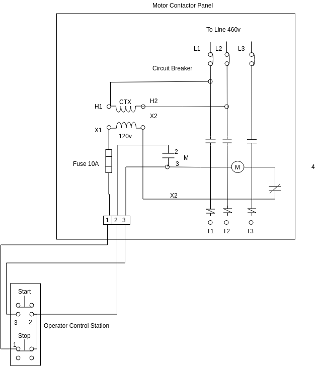
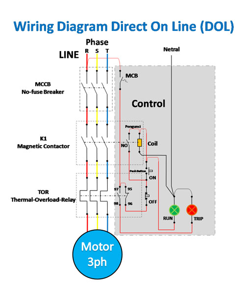
A wiring diagram is a type of schematic which uses abstract photographic symbols to show all the affiliations of elements in a system. The above wiring diagram assumes your magnetic starter has a 240v.
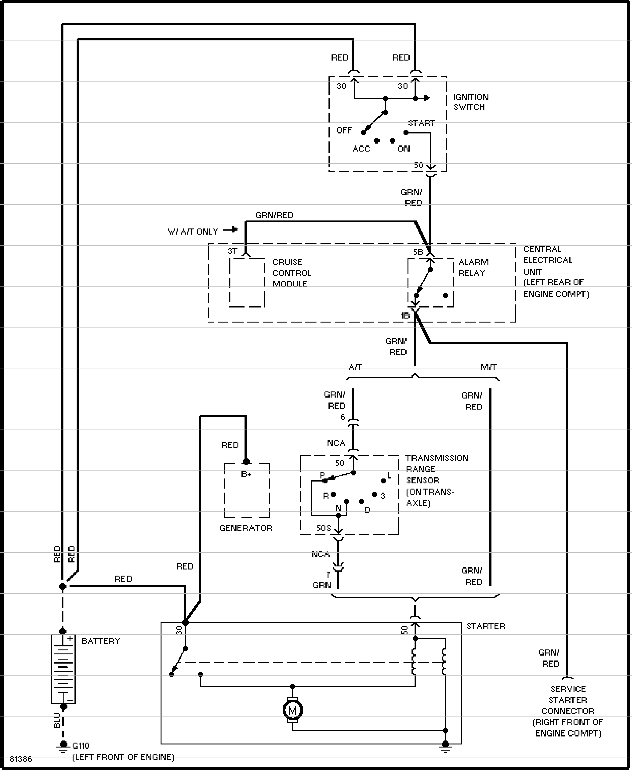
Volvo Start Wiring Diagram Generator 10 Brillenstudio
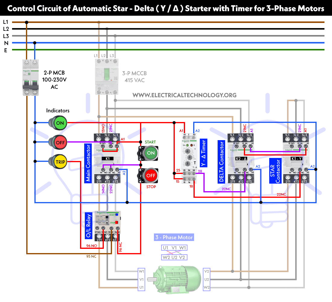
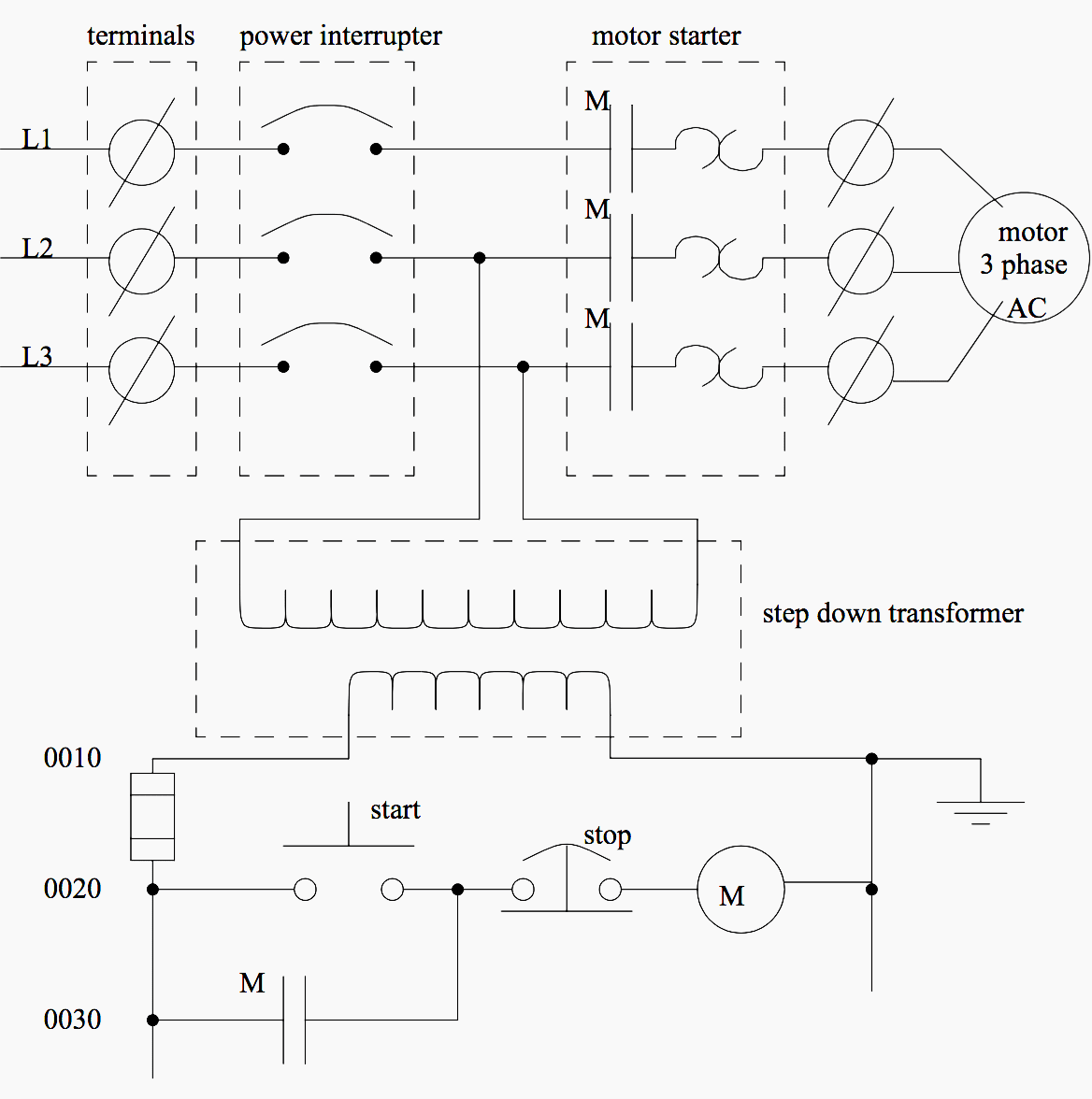
Manual motor starter wiring diagram. They are used in applications which do not require undervoltage protection. Symbols that represent the components inside the circuit and lines that represent. December 8 2018 by larry a. A wiring diagram is a type of schematic which uses abstract pictorial symbols to demonstrate all the interconnections of components in the system. The following diagram depicts 3 phase non reversing motor control with 24 vdc control voltage and manual operation. Wiring diagrams contain a pair of things.
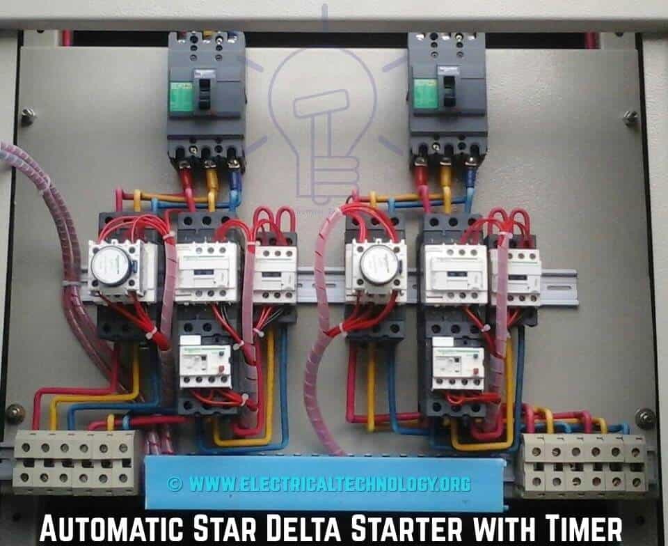
Manual motor starters are simply manual switches designed to control larger current loads typical of motor control. It shows the elements of the circuit as simplified forms and also the power as well as signal connections between the devices. We will use a contactor an auxiliary contact block an overload relay a normally open start pushbutton a normally closed stop pushbutton and a power supply with a fuse. Signs that represent the elements in the circuit and lines. A wiring diagram is a simplified traditional pictorial depiction of an electric circuit. They may be small and similar to the light switches in your home or they may be much larger dedicated switches designed for control of high amperage circuits.
Square d manual motor starter wiring diagram whats wiring diagram. Square d manual motor starter wiring diagram trusted wiring diagrams exactly whats wiring diagram. Circuitry layouts are made up of two points. Wiring diagrams bulletin 609 manual starters are operated by start stop push buttons mounted on the front of the starter. Two speed manual motor starter is designed for starting protecting small single phase two speed ac fan motors. Wellborn variety of square d manual motor starter wiring diagram.
Gallery of Manual Motor Starter Wiring Diagram