Basics 5 480 v mcc 1 line. Basics 9 416 kv pump schematic.

Mcc Panel Ziri Electrical Frequency Inverter Varaible
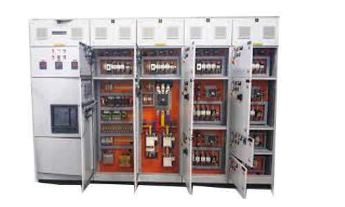
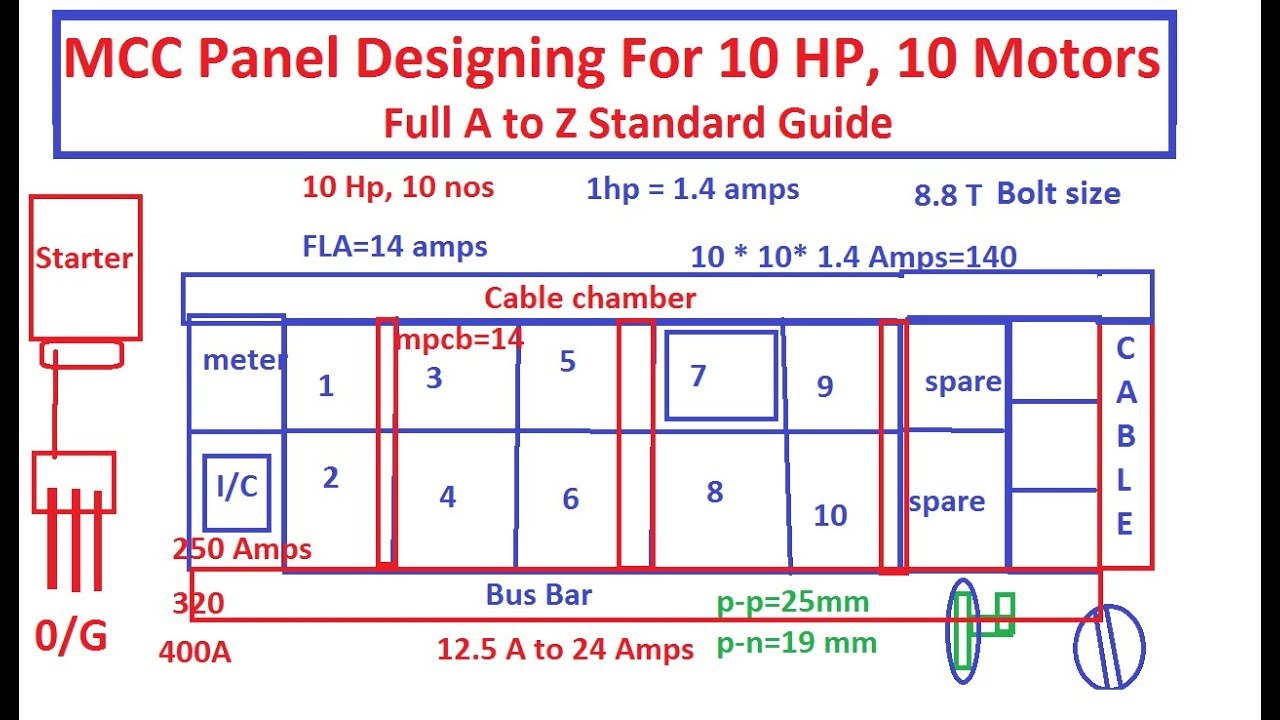
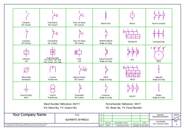
Mcc panel wiring diagram. Basics 13 valve limit switch legend. Basics 8 aov elementary block diagram. Motor control centers are simply physical groupings of combination starters in one assembly. The height of the standard version is 2300 mm 906 in while the compact version is 2200 mm 866 in. Tiastar mcc high density. Tiastar mcc identification guide.
Basics 10 480 v pump schematic. Siemens tiastar industrial motor control centers mcc combine time proven designs and components with the latest in technological advances to meet most applications. T 245 rev a 01 capri 180 capri 280 advantage and capri 280 advantage wide t 250 68rm40 504 514524 t 254 rev a 01 68rm45 104 604704 t 256 68rf4050 t 263 68rm35 104604704 t 264 68rm50 100101102 t 269 68rf50 articulated coach t 270 dm 4 power pack t 271 68rf50 neoplan la t 274 rev a 01 68rm40 108118128 with electronic thermostat. Mns mcc is available in two 2 different versions. Basics 11 mov schematic with block included basics 12 12 208 vac panel diagram. The major difference is the section height and the size of the horizontal wireways.
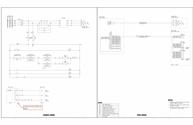
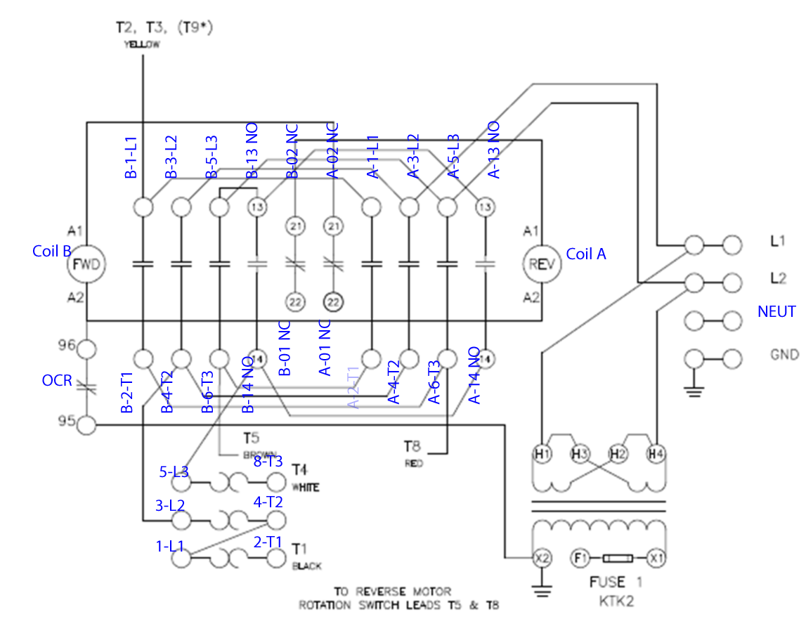
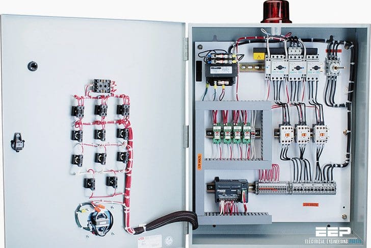
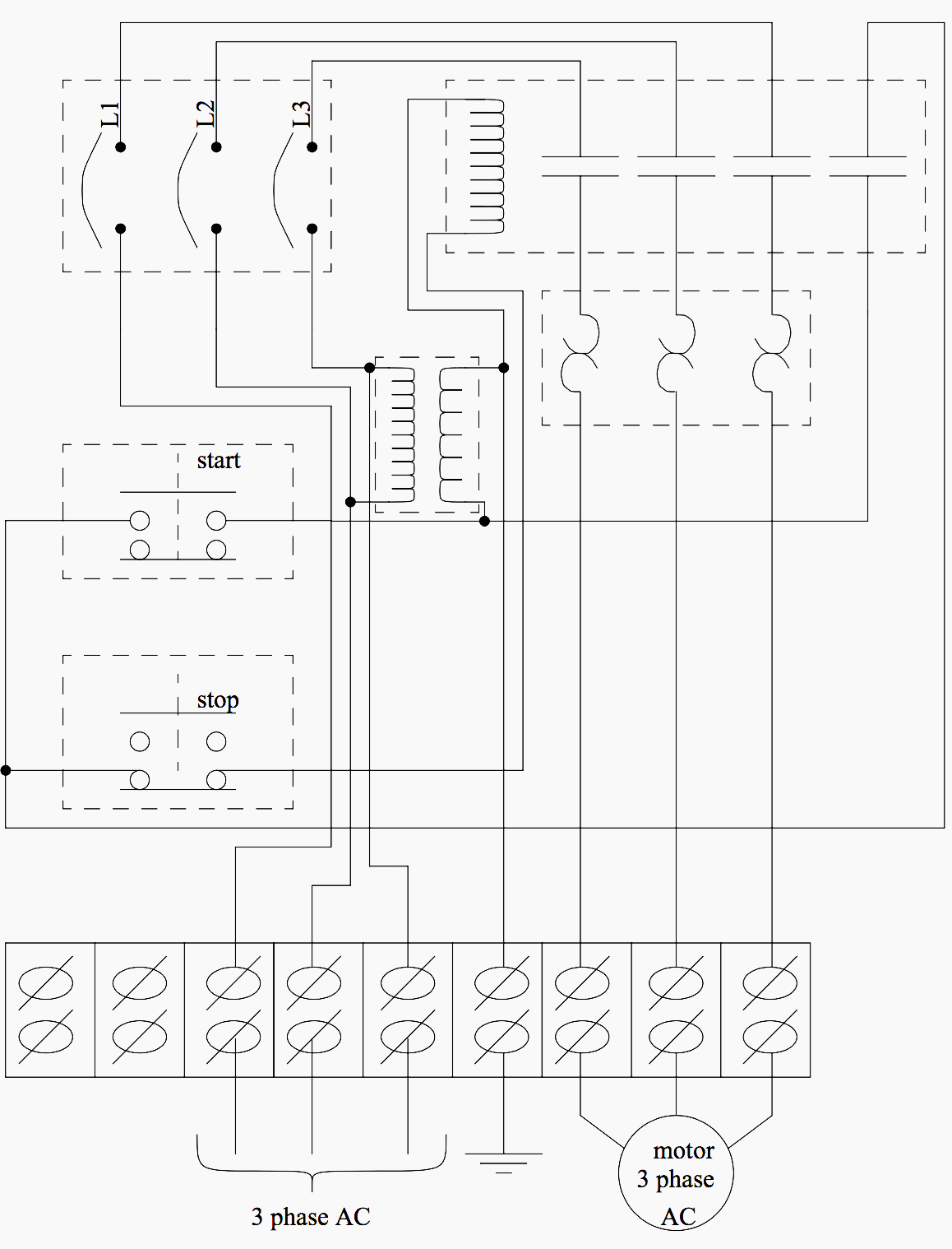
The standard mcc section width is 500 mm 197 in in a front mounted configuration. The contacts m will be controlled by the coil mthe output of the motor starter goes to a three phase ac motor. Three phase motor connection schematic power and control wiring installation diagrams. Tiastar mcc integrated drives. The wiring from a buckets terminal block to master terminal block is completed at the factory. A combination starter is a single enclosure containing the motor starter fuses or circuit breaker and a device for disconnecting power.
Tiastar mcc catalog and application guide. Three phase motor connection stardelta without timer power control diagrams. No matter how customized your needs may be you can be assured that you are getting a finished product that represents the state of the art in low voltage motor control technology. Figure 1 a motor controller schematic. The apparatus designed for this function is the motor control center mcc. Basics 7 416 kv 3 line diagram.
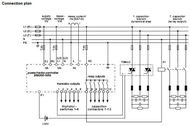
Basics 6 72 kv 3 line diagram. Tiastar mcc expanding installation possibilities with additional network connectivity. The lower voltage is then used to supply power to the left and right rails of the ladder below. Star delta y δ 3 phase motor starting method by automatic star delta starter with timer. Tiastar mcc more than motors. Power is supplied by connecting a step down transformer to the control electronics by connecting to phases l2 and l3.
Tiastar mcc rugged reliable and high performance. The user makes all fields wiring connection at mater terminal block. Figure 3 power cable mcc bucket horizontal wire way control terminal blocks power terminal blocks circuit breaker disconnect.
Gallery of Mcc Panel Wiring Diagram