Diagram 1 1 three phase supply 230volt coil see wiring diagram 1. Dol starter wiring diagram.

Mem Dol Starter Wiring Diagram
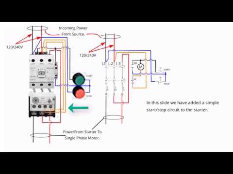
Mem dol starter wiring diagram. Wiring an mem starter for 240v lathe. 3 phase motor wiring diagram fresh mem dol starter wiring diagram motor starter wiring diagram start stop reference start stop switch a pcb from another source can be used in replacing the electronics in a standard device or giving communications to a custom controller. A2 13 17 with a flying lead to be connected to overload terminal 95. Wiring of dol starter 1. The dol starter comprises of an mccb or circuit breaker contactor and an overload relay for protection. L2 of contactor connect no to y phase through mccb.
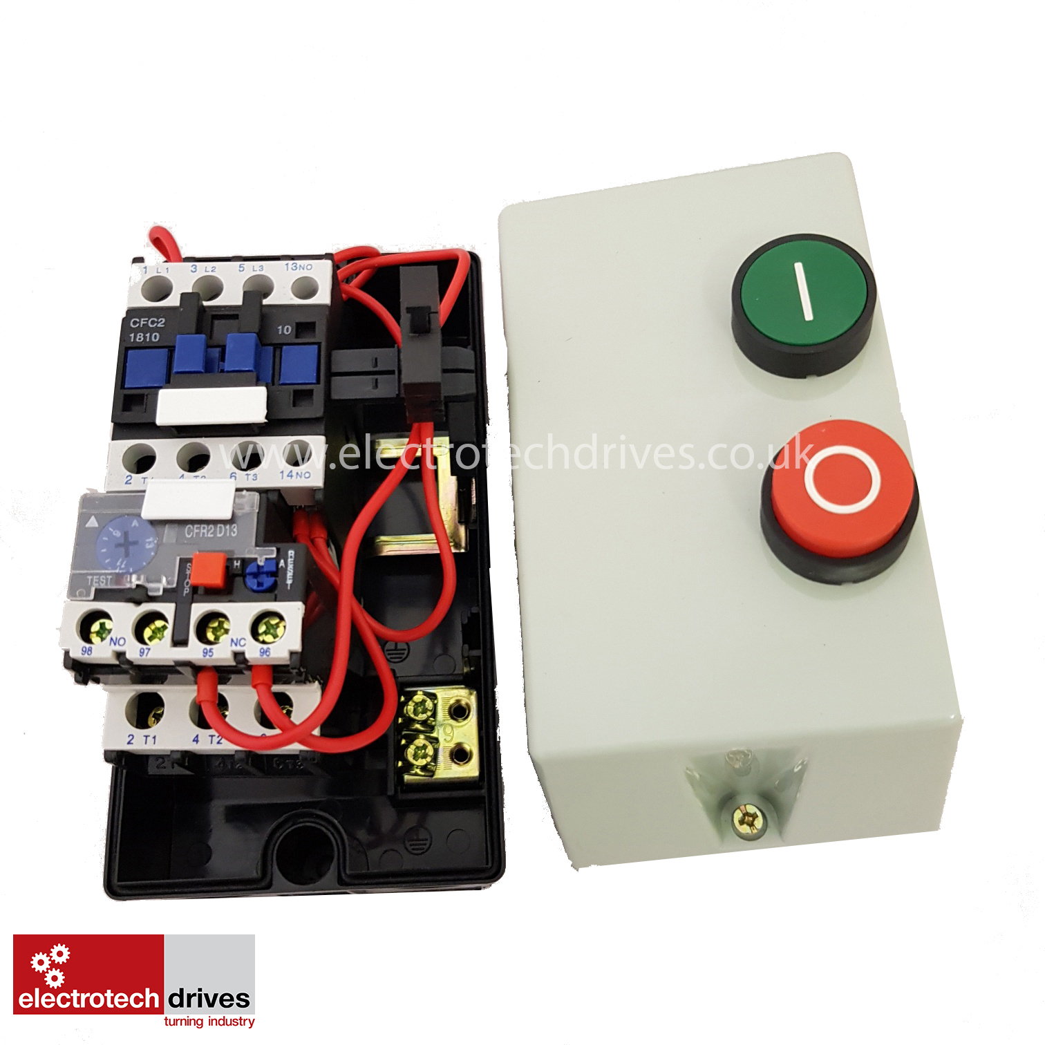
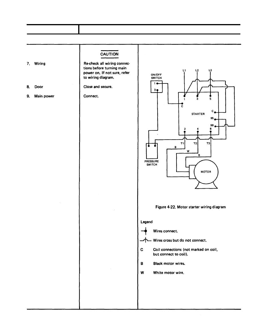
The most common for small direct on line starters dols is 415vac as this requires no neutral to be fed to the starter. The above diagram is a complete method of single phase motor wiring with circuit breaker and contactor. A direct online starter consits of two buttons a green button for starting and a red for stopping purpose of the motor. The following links are pre fitted to the starter. 2 three phase supply 400 volt coil see wiring diagram 2the following. In the above three phase dol starter wiring diagram.
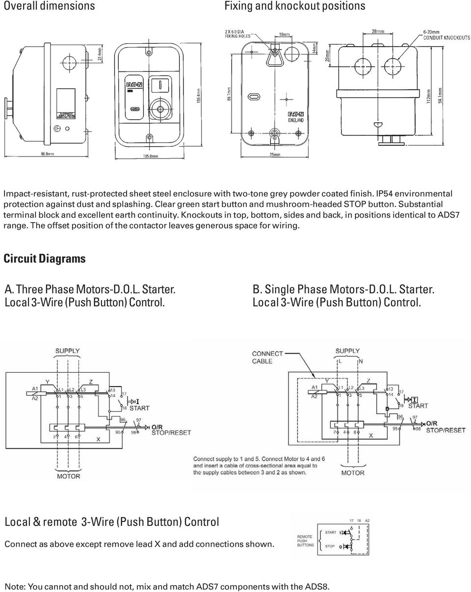
A full voltage non reversing 3 phase motors. They show diagrams for 240 and 415 vac control. In the below dol starter wiring diagram i shown a molded case circuit breaker a magnetic contactor normally open push button normally close push button switch thermal overload relay motor trip indicator and 3 phase motor. Attached is a pdf file with pictorial diagrams 1 of how you would connect the four most common variants of a dol starter. Other brands of contactors may be wired the same or similarly. There are four basic wiring combinations.
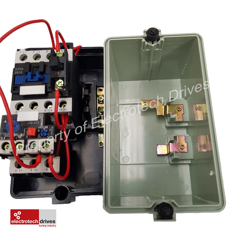
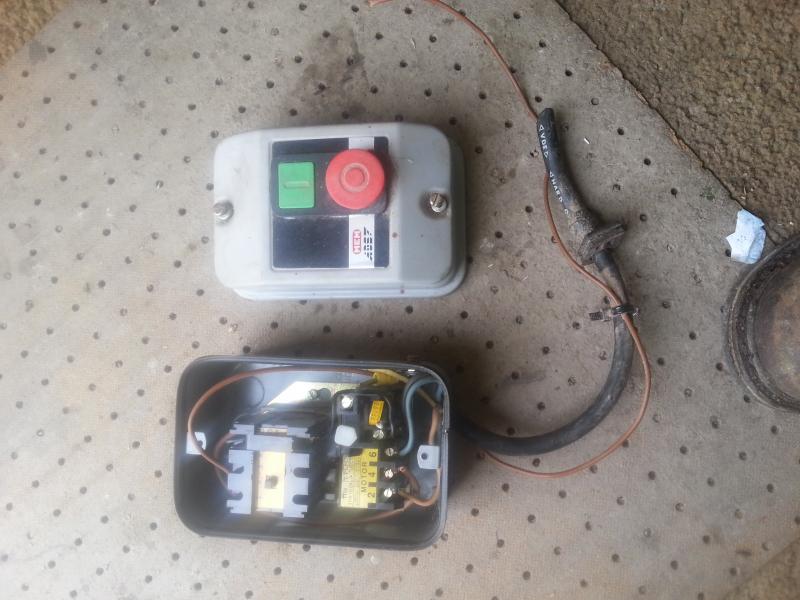
In the above one phase motor wiring i first connect a 2 pole circuit breaker and after that i connect the supply to motor starter and then i do cont actor coil wiring with normally close push button switch and normally open push button switch and in last i do connection between capacitor start motor and contactor. Usually there was a wiring diagram stuck under the cover somewhere. Contactor is connecting among supply voltage relay coil and thermal overload relay. Consult the manufacturers wiring diagrams for other brands of contactors. A2 14 18. The wiring diagram for a dol stater is shown below.
Ive used 3 phase ones on single phase by just wiring up one set of contacts i seem to remember even going to the trouble of rewinding a solenoid to run on 240 volts as the one inside was 440 and didnt have enough pull. L1 of contactor connect no to r phase through mccb. This article shows how to wire various motors using the fuji series of contactors sold by automationdirect. All connection i shown with complete guide. L3 of contactor connect no to b phase through mccb. Reverse forward motor starter control and power circuit with diagram motor windingstar delta starterdol starterstar delta connection3 phase dol starter connection diagram direct online starter.
All other control and power connections have to be made by the installer.
Gallery of Mem Dol Starter Wiring Diagram