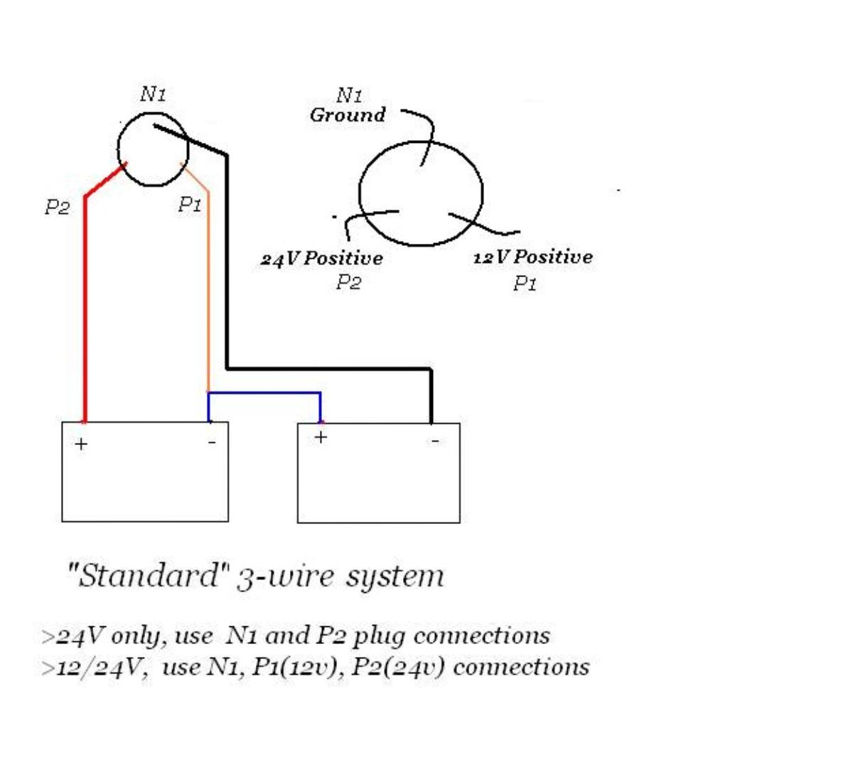
Motor wiring diagram 9 using the motor 10 12 stowing deploying 10. It reveals the parts of the circuit as streamlined forms as well as the power as well as signal connections in between the gadgets.

Wiring Diagram Minn Kota Power Drive 55 I Pilot Wiring
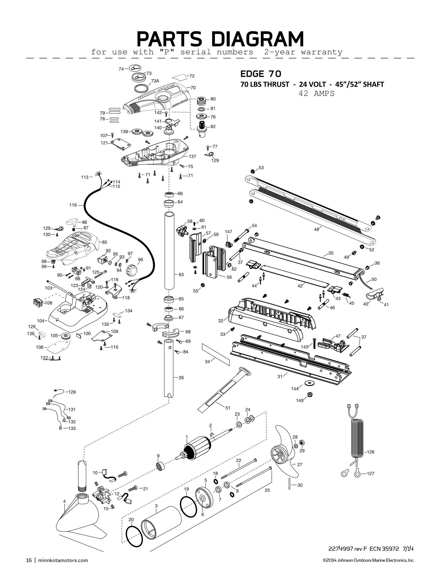
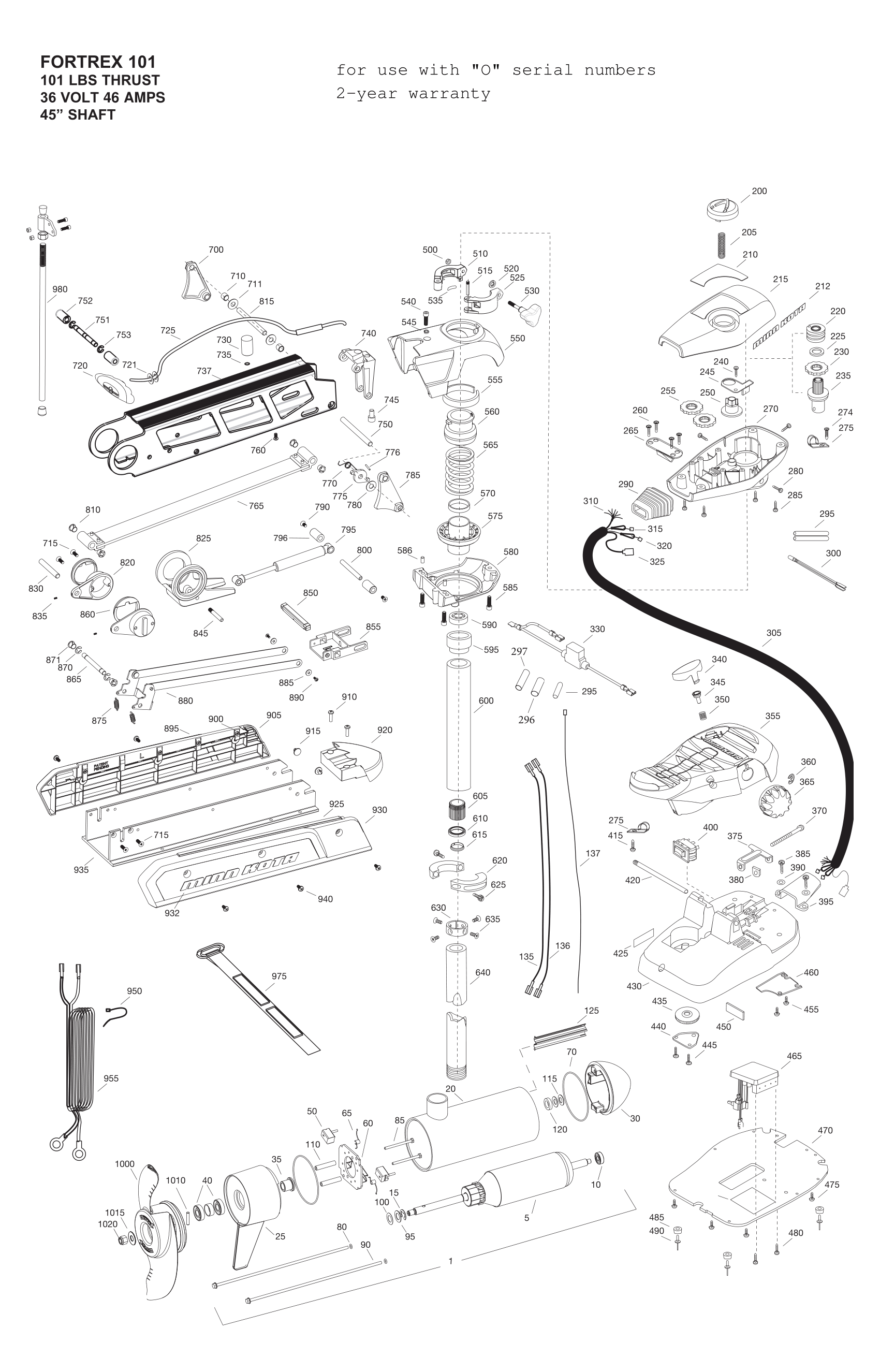
Minn kota foot pedal wiring diagram. Edge trolling motor product manuals foot control models. Adjusting the depth of the motor 11 installing an external transducer 12 using the foot pedal 13 service maintenance 14 troubleshooting 15 parts diagram 16 parts list 17 environmental compliance statement 18. Minn kota trolling motor schematics. You can find your model year in the form below. Wiring diagram minn kota power drive foot pedal for alluring blurts me and minn kota trolling motor wiring free download diagrams lovely for foot pedal diagram. Minn kota limited two year warranty on the entire product.
The motor can also be controlled by an i pilot remote or a compatible minn kota remote if applicable. Get free help tips support from top experts on minn kota wiring diagram related question about trolling motor 65 lb powerdrive v2 54 inchshaft 65 lb. Please refer to the i pilot or compatible remote manual on how the remote controls the motor. Minn kota corded foot pedal owners manual 24 pages. However with circuit board costs rising it is more important than ever to correctly diagnose the problem before replacing parts. Batteries between one three 12v batteries depending on the voltage of the trolling motor.
Minn kota repair manual 103102 iii trouble shooting tips with all the new features and models being added to our minn kota line motor troubleshooting and repair can be quite complicated. Related manuals for minn kota corded foot pedal. Trolling motor control hand tiller foot pedal or remote control power leads with terminal ring battery connectors 5 for minn kota and 3 for motorguide motors additional equipment required. Also see for minn kota corded foot pedal. All orders placed before 2 pm cdt monday thru friday will ship that same day. Variety of minn kota trolling motor wiring diagram.
A wiring diagram is a simplified standard photographic depiction of an electric circuit. The foot pedal is used to operate the motor and controls on the foot pedal are easy to operate by either foot or hand. Edge 45 lb 364550 foot control product manual manual 2274994 download pdf 7 mb edge 55 lb 4555 foot control product manual. See our battery selection guide. If you cant find what youre looking for or have questions please give us a call at 7155462333. This section is broken down by model year.
For model years before 1991 please us e the folder called older motors.
Gallery of Minn Kota Foot Pedal Wiring Diagram