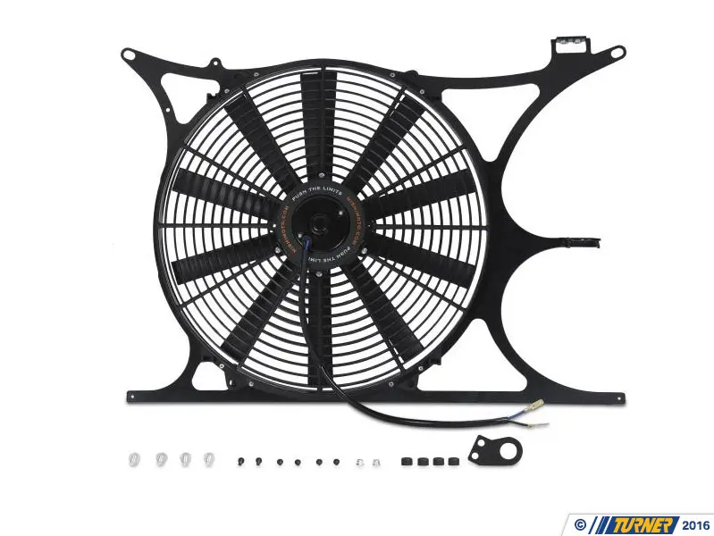
Mishimoto has the solution. With either a mishimoto slim electric fan or a race line high flow fan combined with an optional mishimoto adjustable fan controller kit youre guaranteed higher cfm maximum cooling power and a sleek look.
How To Install A Mishimoto Electric Fan Nasioc
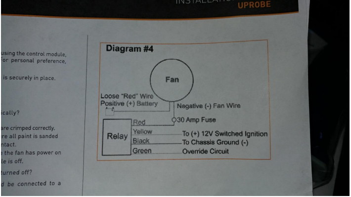
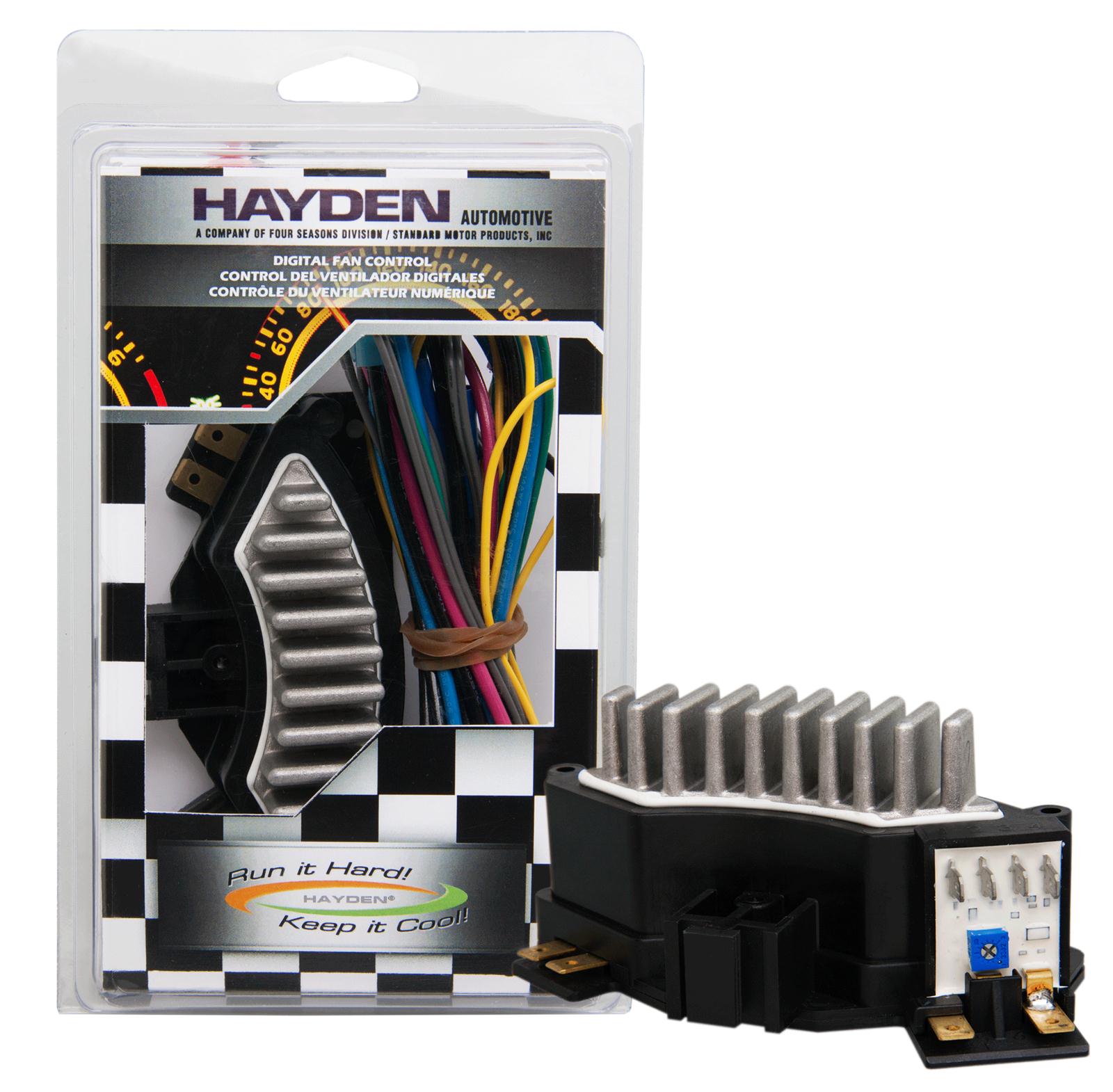
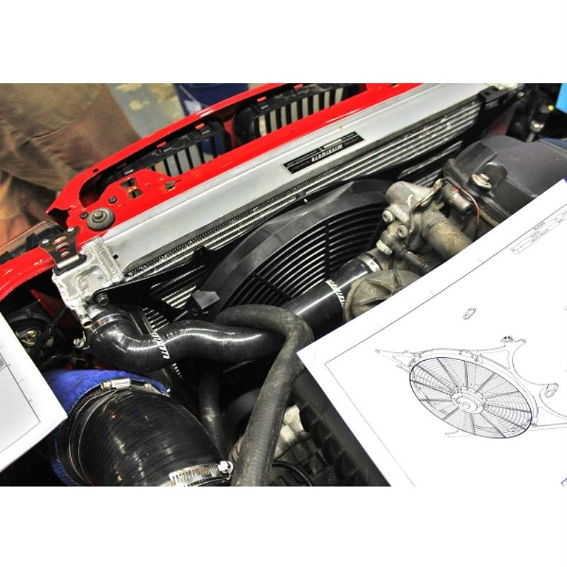
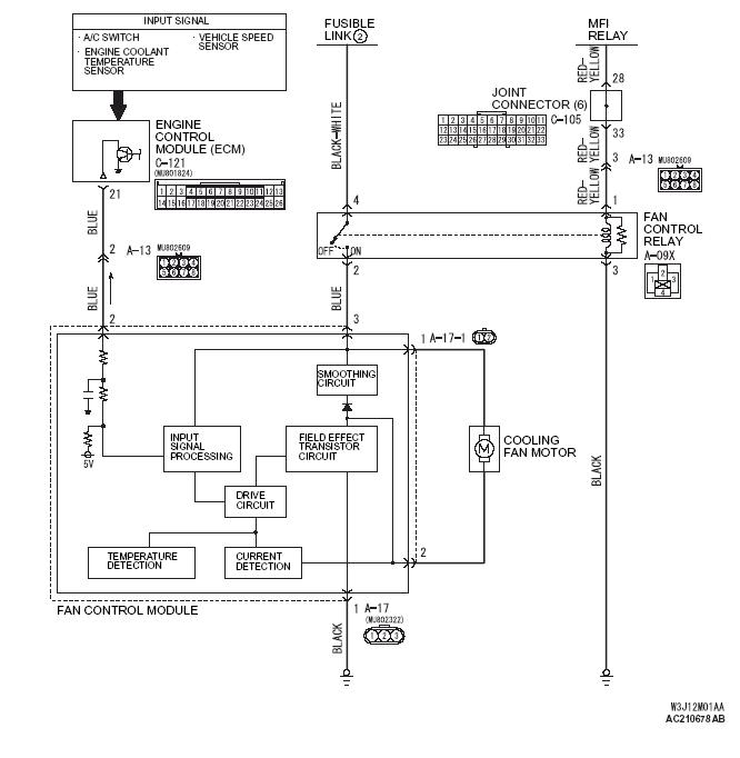
Mishimoto fan controller wiring diagram. Mishimoto fan controller. Variety of mishimoto fan controller wiring diagram. The mishimoto fan controller features adjustable activation from 150f to 240f and deactivates once temperatures are reduced by 10f. He wanted to do away with the old viscous fan and stock thin rad so we installed a big alloy radiator with. A wiring diagram is a simplified standard photographic depiction of an electrical circuit. Mishimoto fan controller wiring diagram architectural circuitry layouts reveal the approximate areas and also affiliations of receptacles illumination as well as irreversible electrical solutions in a structure.
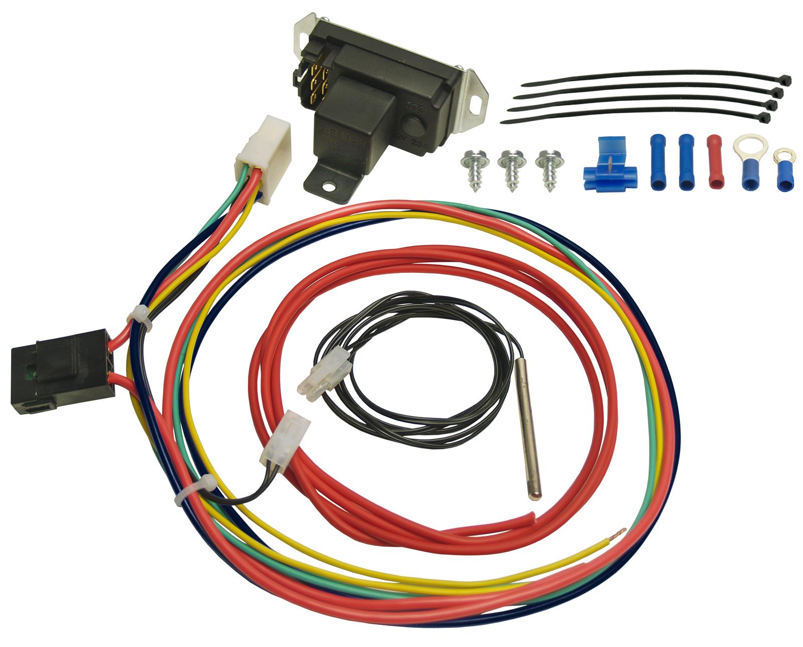
Plug in the wire harness into the fan control module. This controller includes a built in ac override feature and is designed for use with 12 electric fans drawing a combined 25 amps or less. Helping a friend of mine with his r33 nissan skyline gtst. Interconnecting cord paths may be revealed about where certain receptacles or components have to get on a common circuit. See diagram 3 01 adjustable electric fan controller parts list and installation guide u18npt continued on following page rill 532 drill bit thread sealant tape 12v test light standard screwdriver or. A wiring diagram is a simplified conventional pictorial representation of an electric circuit.
It reveals the elements of the circuit as simplified forms as well as the power and signal connections in between the tools. Assortment of mishimoto fan controller wiring diagram. Using the electrical connectors and wire ties provided follow the instructions below. It reveals the parts of the circuit as streamlined forms and the power and signal links between the tools.
Gallery of Mishimoto Fan Controller Wiring Diagram