Replacement ceiling fan remote control receiver module. Gallery of mr77a wiring diagram download assortment of mr77a wiring diagram a wiring diagram is a streamlined standard photographic depiction of an electric circuit it reveals the elements of the circuit as simplified forms as well as the power and also signal connections between the devices a wiring diagram normally offers info concerning the family member placement and plan of tools and.

93 Ford Thunderbird Fuse Box Diagram 1997 Ford Thunderbird
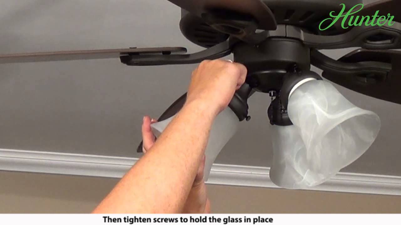
Mr77a wiring diagram. But most important the capacitors in their replacement will be 6uf 6uf. My controller model number was mr77a just for reference. Some are selling a replacement for this mr77a ceiling fan receiver. I had this wired up and it was working with a fanlinc. Use the wire balldownrod figure 8. Before installing the receiv wires from this fan.
It reveals the elements of the circuit as simplified forms as well as the power and also signal connections between the devices. One switch is for the light the other may be a fan speed control dimmer after having lived with it for a few months im considering removing my dimmer and turning it to a simple onoff. The mr77a has 6uf 9uf. A wiring diagram is a streamlined standard photographic depiction of an electric circuit. Hampton bay or hunter ceiling fan remote re wiring for wall control duration. 26082018 26082018 0 comments on mr77a wiring diagram.
Assortment of mr77a wiring diagram. Replacement mr77a hampton bayhome decorators collection ceiling fan kit direct replacement very easy installation and the fan is working againdonna steering column wire diagram check the attached linksinstruction and guides good luck. Hampton bay ac wiring diagram. Collection of mr77a wiring diagram. The conversion outlined will require 2 switches and 3 wires black red white ground going to your ceiling fan. Simple diagram for those of you thats receiver burned out and the company wont help you.
It shows the elements of the circuit as streamlined forms and the power and signal connections in between the gadgets. This video shows you how to remove to the original receiver and replace it with the new updated version 2 mr77a receiver. I could turn it on. A wiring diagram is a simplified standard pictorial depiction of an electric circuit. Setting the code each wire nut wire connector sup the frequencies on your receiver and plied with this fan is designed to accept transmitter have been preset at the up to one 12 gauge house wire and two factory. Does anyone have some sort of diagram that might help my wire up what hes describing.
Hampton bay or hunter ceiling fan remote re wiring for wall control. The fan will require modifications to make this receiver fit.
Gallery of Mr77a Wiring Diagram