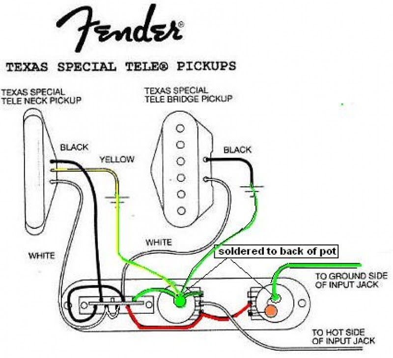
Expert of finnish design moderator of rmysummercar speaking officially 16 points 2 years ago. All of the wires of the msd ignition may be shortened as long as quality connectors are used or soldered in place.
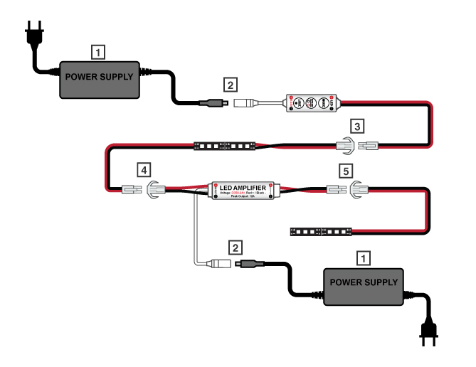
Single Color Led Mini Amplifier Lc2 Connector
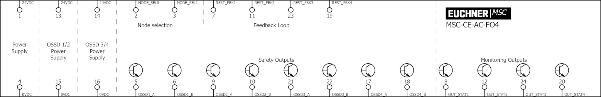
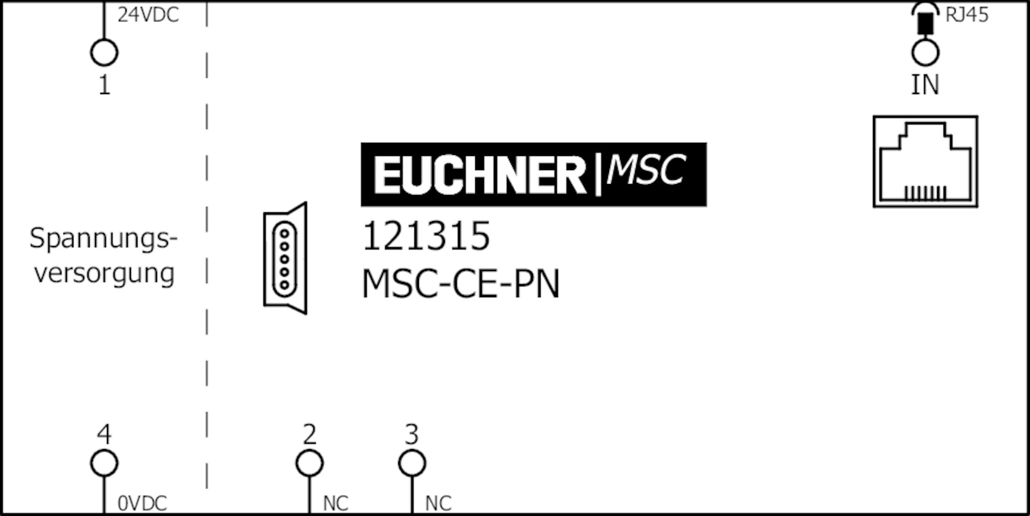
Msc wiring diagram. 1. This thread is archived. Lower the mounting template onto the pad setting the l bolts into concrete. To lengthen the wires use one size bigger gauge wire 10 gauge for the power leads and 16 gauge for the other wires with the proper connections. The purpose of recommending msc message sequence chart is to provide a trace language for the specification and description of the communication behaviour of system components and their environment by means of message interchange. Wiring general wiring information wire length.
All connections must be soldered and. Service manual mitsubishi electric msc 12rv service manual 186 pages wireless multi system inverter controlled multi system type split type heat pump air conditioners. Pour the concrete pad around the properly positioned sweep ells. Wiring general wiring information wire length. Wiring valve common wires master valve wiring ground wire etc. My summer car tutorial.
All of the wires of the msd ignition may be shortened as long as quality connectors are used or soldered in place. Johtonippu is an item that can be found inside the garage at home. All connections must be soldered and. We have 4 mitsubishi electric msc 12rv manuals available for free pdf download. How to connect the eletrical system. Never leave the groundnegative bolt bolted in on its own.
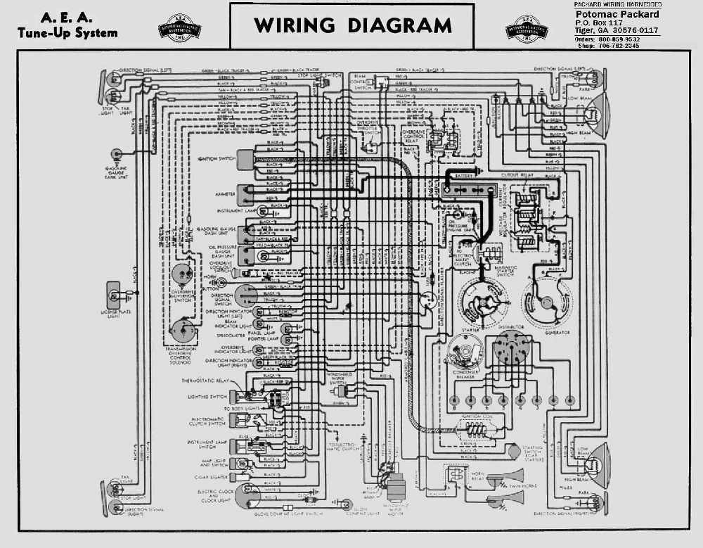
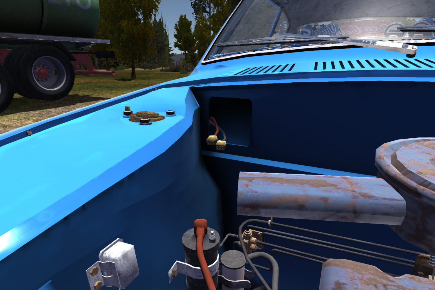
To lengthen the wires use one size bigger gauge wire 10 gauge for the power leads and 16 gauge for the other wires with the proper connections. A quick tutorial on how to setup the new eletrical system for the satsuma. When you finish wiring the car you must bolt in the battery. A message sequence chart or msc is an interaction diagram from the sdl family standardized by the international telecommunication union. The wiring mess. Wiring diagram 2 multi location wiring model msc ad msc 600m msc 1000m msc 600m msc 1000m or control line side neutral red blue multi location dimmer smart remote smart remote smart remote hot black black up to nine total auxiliary switchesremotes 120vac 60hz green green green greenblue red black blue red black blue lighting load red grou wire smart remote smart remote.
Bolting the ground side first will lead to a likely battery fire. It is used to wire up satsumas critical components as well as accessories. Wires can be attached by holding the wiring mess on top of a partconnector pressing f when the check mark icon appears then holding it on top of another partconnector and doing the same. There are a total of 26 wires that can be. New comments cannot be posted and votes cannot be cast. Run all power wires communication wires and field wiring through their appropriate conduits.
First bolt in the positive side with an 8mm. Satsuma wiring diagram not made in paint edition 11 comments. Then and only after bolting in the positive side you can bolt in the ground side with an 8mm.
Gallery of Msc Wiring Diagram