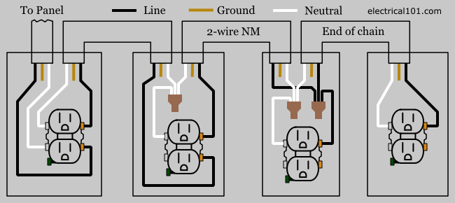
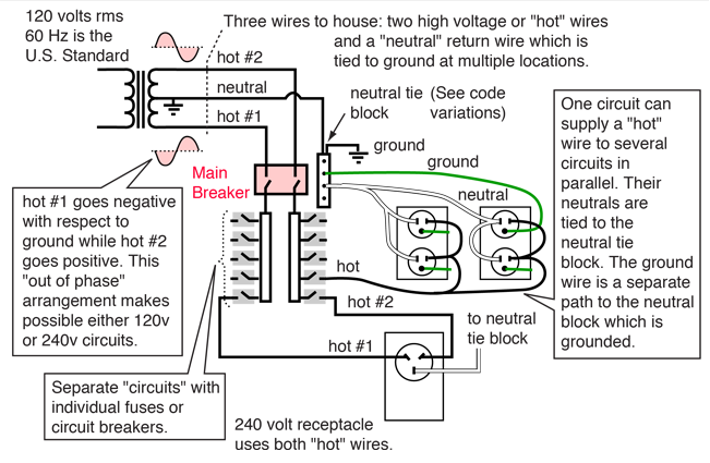
The black hot connection is broken to turn the light onoff the white neutral connection completes the circuit. In the diagram above right both phase a and b breakers or switches are open.
4 Smart Switches That Work With No Neutral Wire
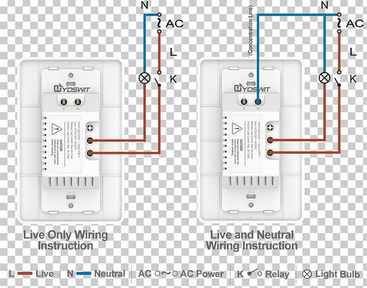
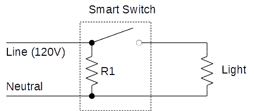
Neutral wiring diagram. The hot and neutral lines should be two distinct colors but the colors can vary for the different wires. Identifying electrical wiring properly is an important step when replacing a light fixture installing an outlet or handling other electrical work. Here is a diagram of a standard switch with a neutral wire. It protects from static build up and from electrical insulation failure in short its only job is to make your home safer. Switch with a neutral wire a smart switch can simply tie into the white neutral wires to complete the circuit and get a source of power to keep the radios in the switch working at all times. Basically wiring used for a a switch is nothing more than a loop which passes through a light switch.
The case that everyone refers to when they say no neutral is when the line voltage comes to the light bulb first. 3 way switch wiring diagram line to light fixtureline voltage enters the light fixture outlet box. The neutral wire on the left side of the open comes from the panel is 0v. No longer allowed after 2011 nec if no neutral wire in switch boxes 3 way switch wiring diagram light fixture between switchesline voltage enters the first 3 way switch outlet box light fixture is located between switch boxesno longer allowed after 2011 nec if no neutral wire in switch boxes. This is shown in the diagram below. In the diagram above left the a phase breaker or switch is open.
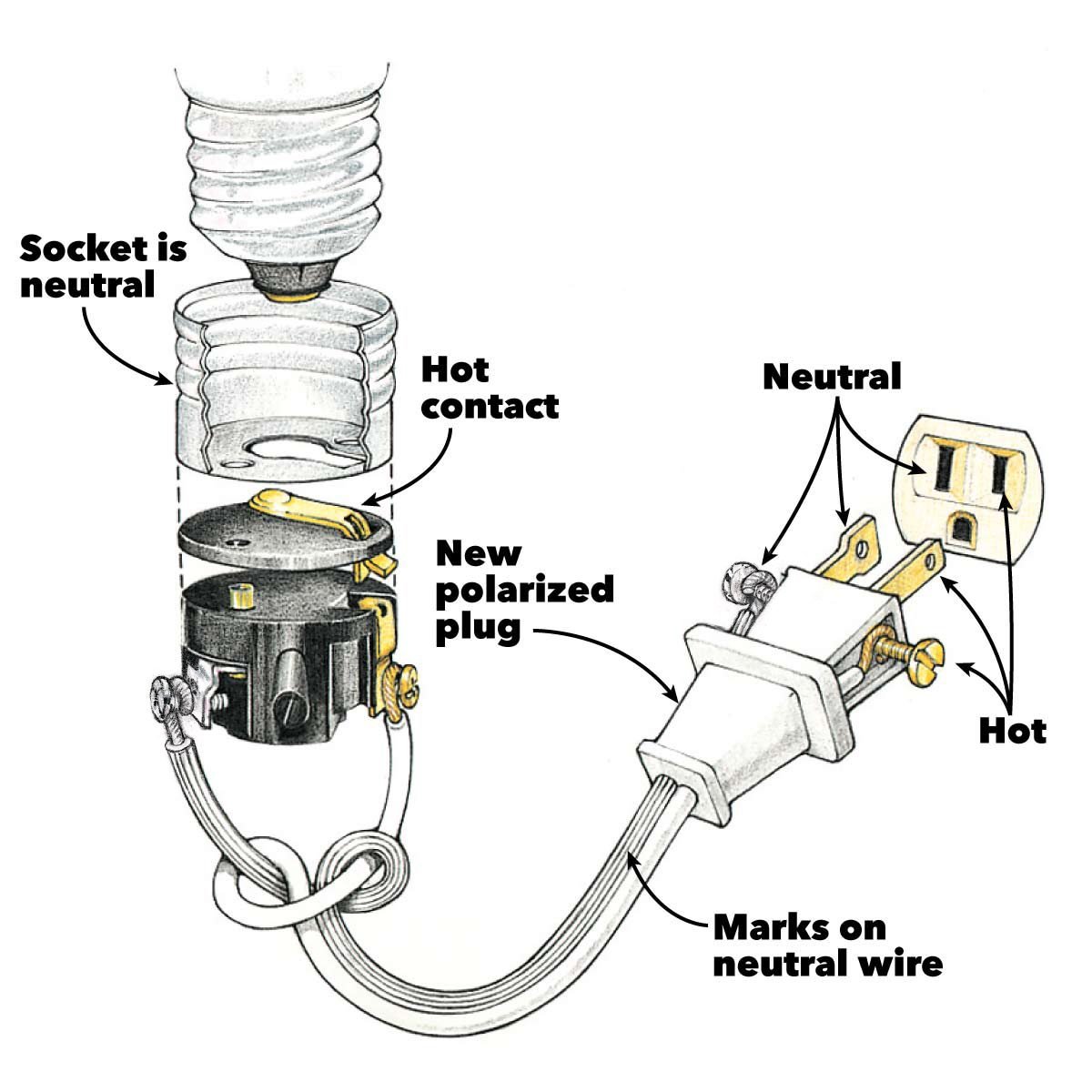
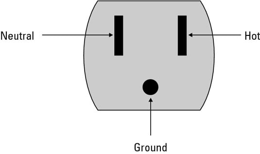
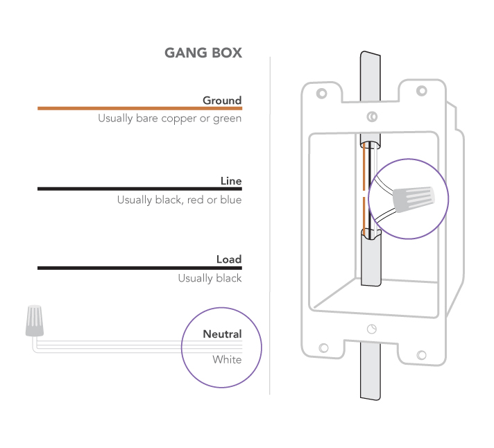
The diagram below shows this configuration this circuit has a neutral. A grounded contact at the bottom center is crescent shaped. The wire on the right side of the open goes to the load is 120v to ground. Learn how to identify wires for your safety. The long slot on the left is the neutral contact and the short slot is the hot contact. This is a diagram of a switch with a neutral.
The bare hopefully solid copper wire is the ground. The neutral is an insulated wire because it is part of the circuit which flows electrical current. This is a standard 15 amp 120 volt wall receptacle outlet wiring diagram. The grounded electrode conductor. Then from the light bulb another loop goes to the switch. This is a polarized device.
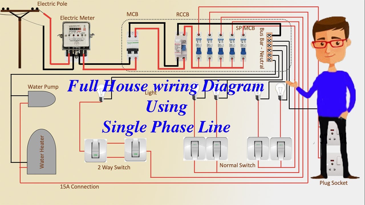
The neutral wire the purpose of the neutral wire is to complete the 120volt ac circuit by providing the path back to the electrical panel where the neutral wire is connected and bonded to the earth ground. How to configure the ground and neutral of electrical wiring first lets make sure that you understand that a neutral wire is not used for a typical single light switch.
Gallery of Neutral Wiring Diagram