Step by step pictures and diagrams to help you install your nitrous kitsystems and components are the quickest and easiest way to get large horsepower increases with a minimum of engine modifications and expense. Includes nitrous purge nitrous bottle heater and dedicated fuel system.
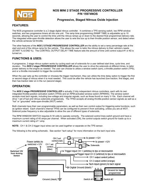
Nos Mini 2 Stage Progressive Controller Mps Racing
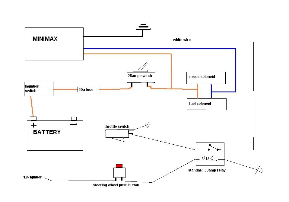
Nitrous oxide wiring diagram. Rpm onoff control eliminates the. Nitrous oxide is for off road use only. Your 1 source for everything nitrous. Featuring two completely independent stages of nitrous control each with its own throttle position activation switch and progressive ramps. Nitrous kits offer serious horsepower at the flip of a switch. I s cnc nitrous bungs annular style nozzles 500.
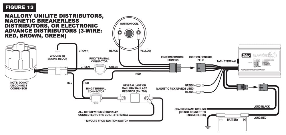
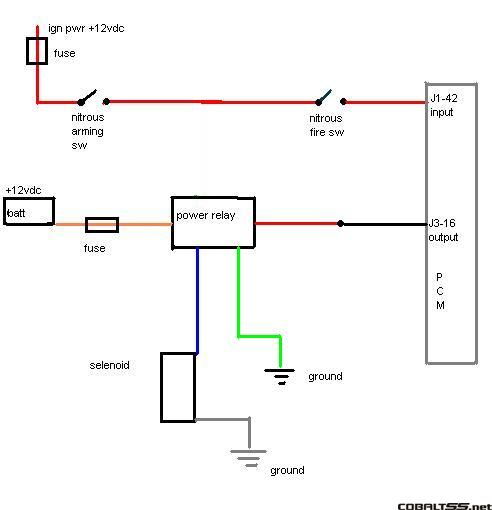
Nitrous oxide install instructions directions. Even though it has nothing to do with nitrous oxide system wiring it is probably a good idea for me to point out that the diagram below shows the yellow wire connected to the coil. It is activated by applying 12volts. Nitrous wiring diagram with transbrake. That should only be done if the coil is connected to a 12 volt source and not being driven by any sort of ignition amplifier or ignition box. 10lb 15lb race ready nitrous.
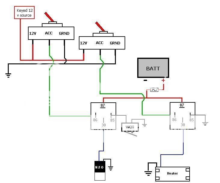
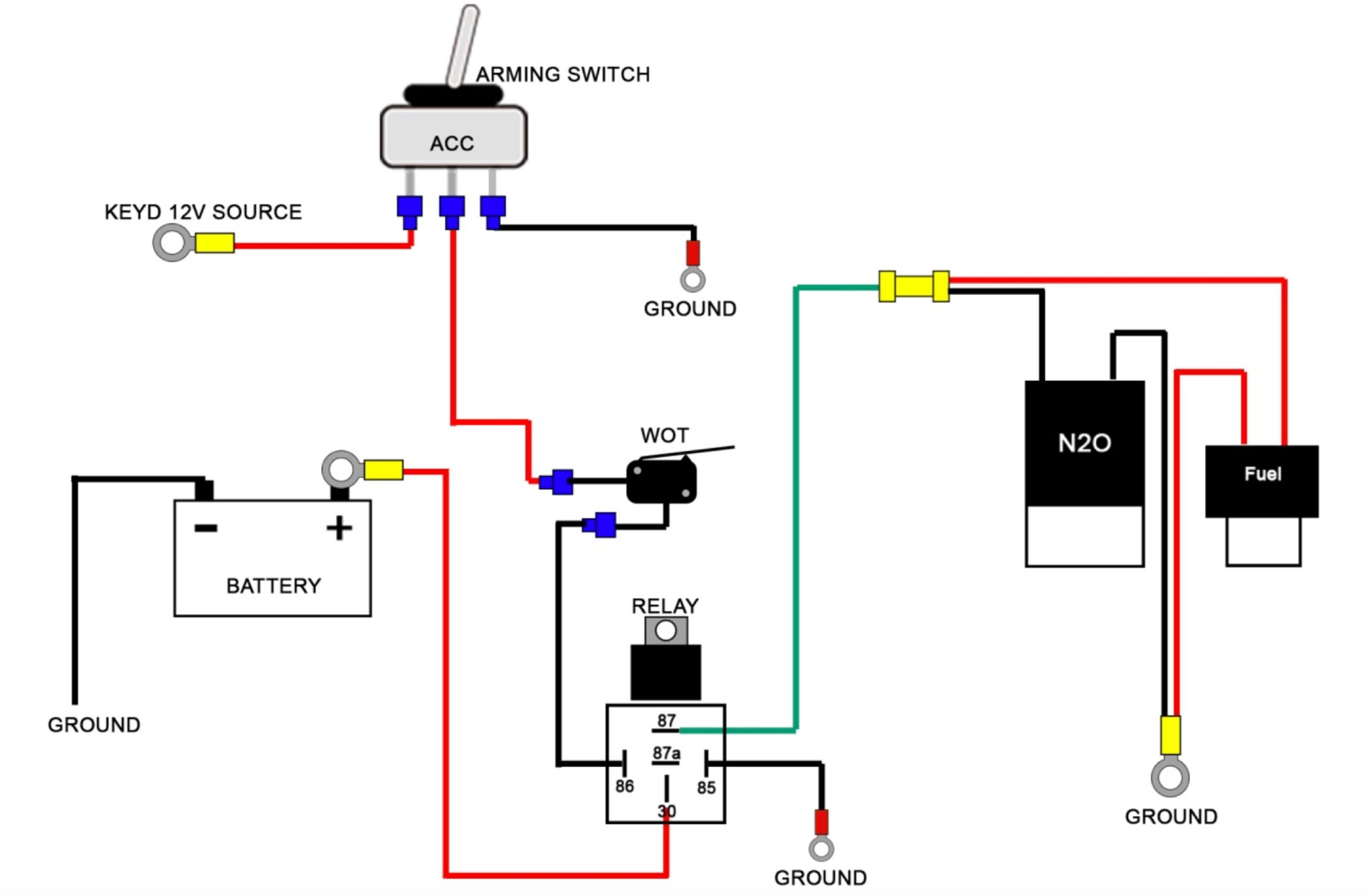
These wiring diagrams will help you wire up your nitrous system or nitrous accessory. High flow quarter turn valve for nitrous oxide systems 5995. Nitrous oxide systems is proud to announce their new mini 2 stage progressive nitrous controller. The stud labeled 2 is for the transbrake. Wiring diagram in illustration d. Toggle navigation 254 848 4300 speak with a nitrous expert m f 830am 530pm cst.
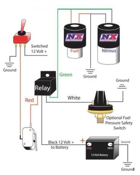
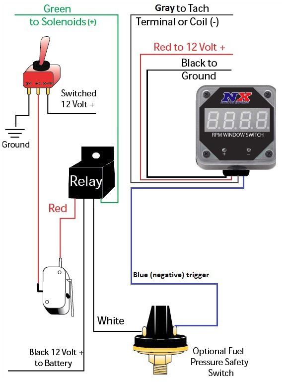
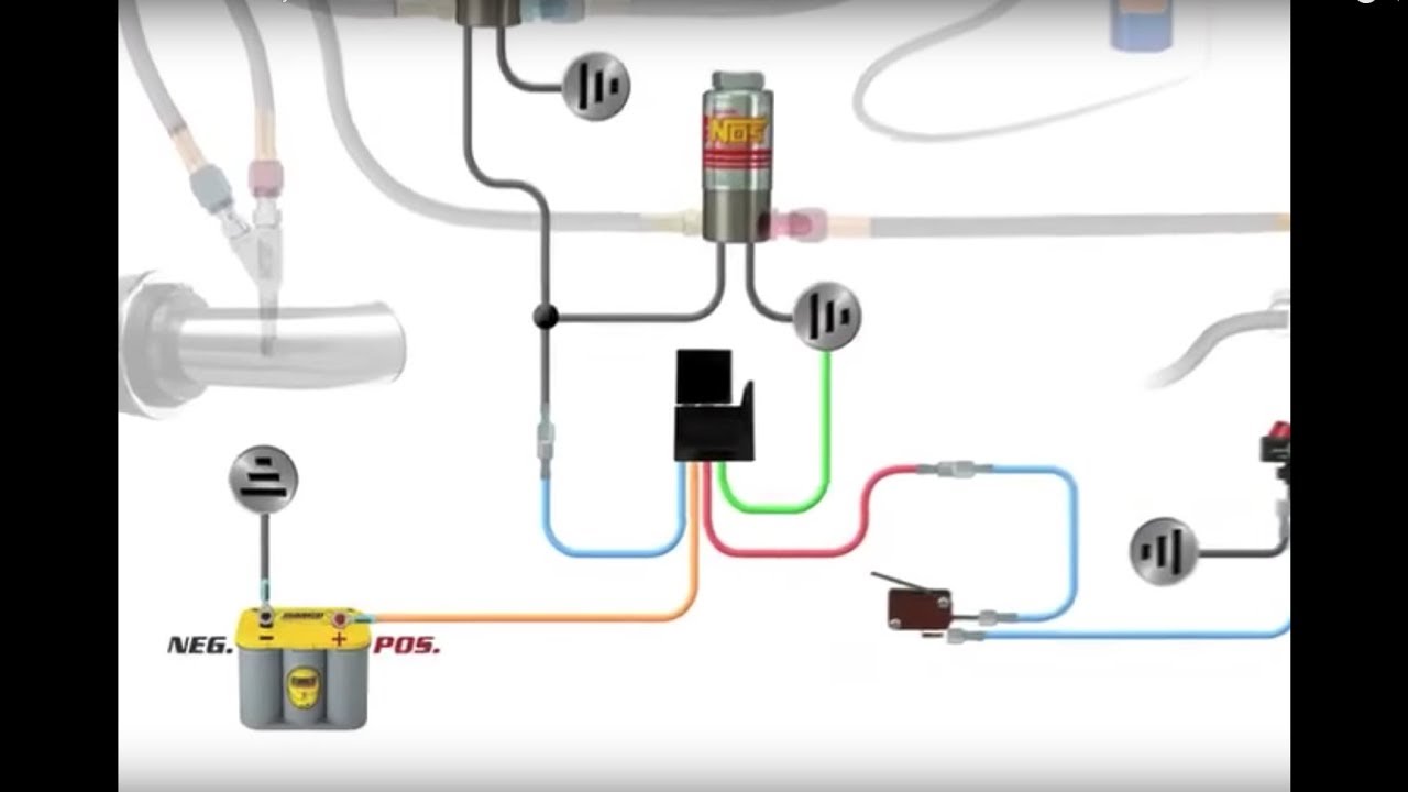
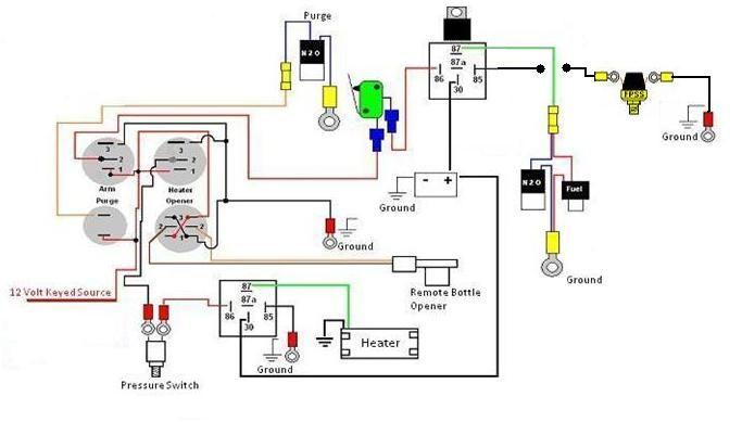
Wiring with and without a progressive controller transbrake wiring with and without a progressive controller no transbrake. It allows you to get the most out of your nitrous system and put more power to the ground when traction is at its best. Responsibility for injuries resulting in the installation of any products. Nitrous oxide wiring diagram of 2 step nos throttle switch and i need to 2 step and transbrake at rpm or so and have my nos. In all applications always use the furnished relay this will insure adequate voltage to the solenoids and take the high amperage load off of the trigger switch. N2o072518 5 basic installation afr wiring diagramafr basic wiring setup diagram arm stage 1 battery 10ga min ground stage 1 stage 2 12v switched tps wideband 2 wideband 1 fuel pressure map n2o pressure 1 stage 2 retard.
Nitrous oxide installation experience nitrous express.
Gallery of Nitrous Oxide Wiring Diagram