Compatible notifier system control panel list available from noti fier. When utilizing switches at voltages greater than 74 vdc or 49 vac means to provide all pole.

Intelligent Control Panel Slc Ppt Video Online Download
Notifier frm 1 wiring diagram. A wiring diagram is a simplified conventional pictorial representation of an electric circuit. Notifier slc wiring manual document 51253. The box must have a minimum depth of 218. Ing power limited and non power limited wiring in the same junction box as fcm 1a. Removing general description rotary switch stop. Maximum slc current draw.
4675 h x 4275 w x 14 d mounts to a 4 square by 218 deep box listings. Compatible notifier system control panels only list available from notifier. Variety of notifier fcm 1 wiring diagram. Mounting the frm 1 mounts directly to 4 square electrical boxes see fig ure 2a. All wiring must conform to applicable local codes ordi. The box must have a minimum depth of 21 8.
Surface mounted electrical boxes smb500 are available. Frm 1a installation document i56 3502. Current rating maximum voltage load description application. 65 ma led on temperature range. Page 5 wiring diagrams this page. Dn 6724 040504 page 1 of 4 fcm 1 module see wiring diagram fig.
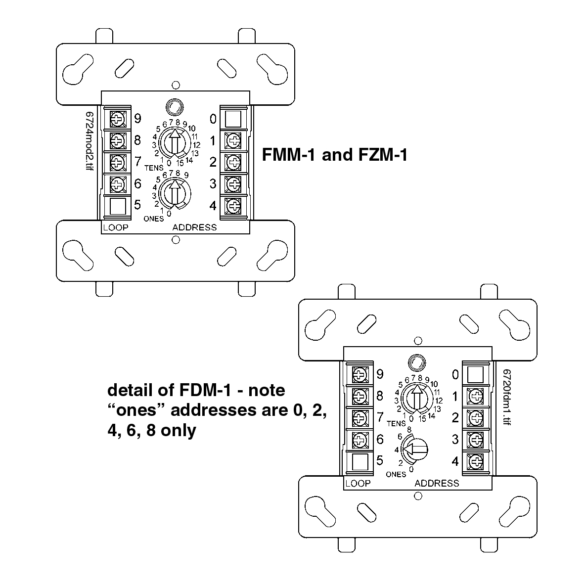
All wiring shown is supervised and power limited. Surface mounted electrical boxes smb500 are available from notifier. The frm 1 relay control module is intended for use in intelligent two wire systems where the individual address of each module is selected using the built in rotary switches. All wiring must conform to applicable local codes ordi. Supervisory switch wiring diagram. Doing so may result in severe injury or death.
Install contact closure devices per manufacturers installation instructions. N770 04 00 1 i56 0393 008r. Mounting the fcm 1 mounts directly to 4 square electrical boxes see figure 2a. Refer to the appropriate notifier control panel installation manual for detailed system information. 15 to 32 vdc. Any number of ul listed contact closure devices may be used.
5 for frm 1 general fcm 1 control module the fcm 1 addressable control module provides notifier intelligent control pan els a circuit for notification appliances horns strobes speak ers etc or to monitor a telephone circuit. Do not handle live ac wiring or work on a device to which ac power is applied. No 460 006 1 i56 3502 003 frm 1 relay control module before installing this information is included as a quick reference installation guide. Fmm 1 connect modules to listed compatible notifier control panels only. If the modules will be installed in an existing operational sys. Summary of contents for notifier frm 1 page 1 figure 1.
32f to 120f 0c to 49c dimensions. For installation instructions see the following documents. It reveals the parts of the circuit as streamlined forms and the power as well as signal links in between the tools. Fcm 1a installation document i56 1169. 4675 h x 4275 w x 14 d mounts to a 4 square by 218 deep box specifications for frm 1.
Gallery of Notifier Frm 1 Wiring Diagram