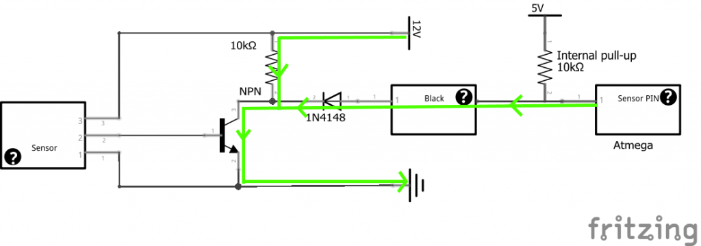
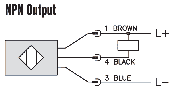
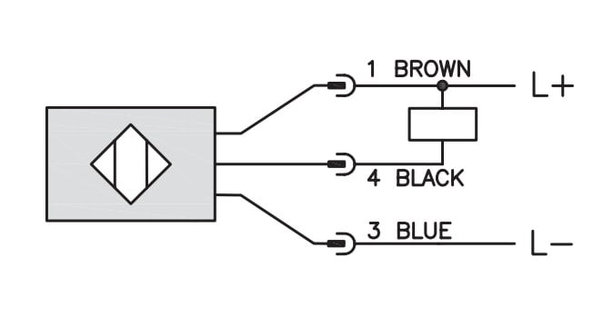
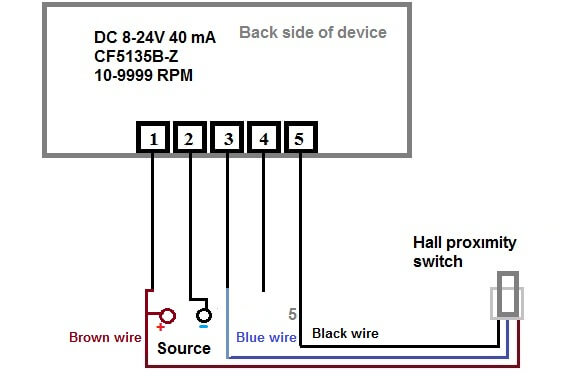
You will notice that the load appears between the v brown and switching wire black. The v brown will be attached to the common input and the switching wire black will be attached to the input number.
M14 Amplifier Outside 18mm Length Housing 3 Wire Sn 4 Npn Or
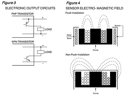
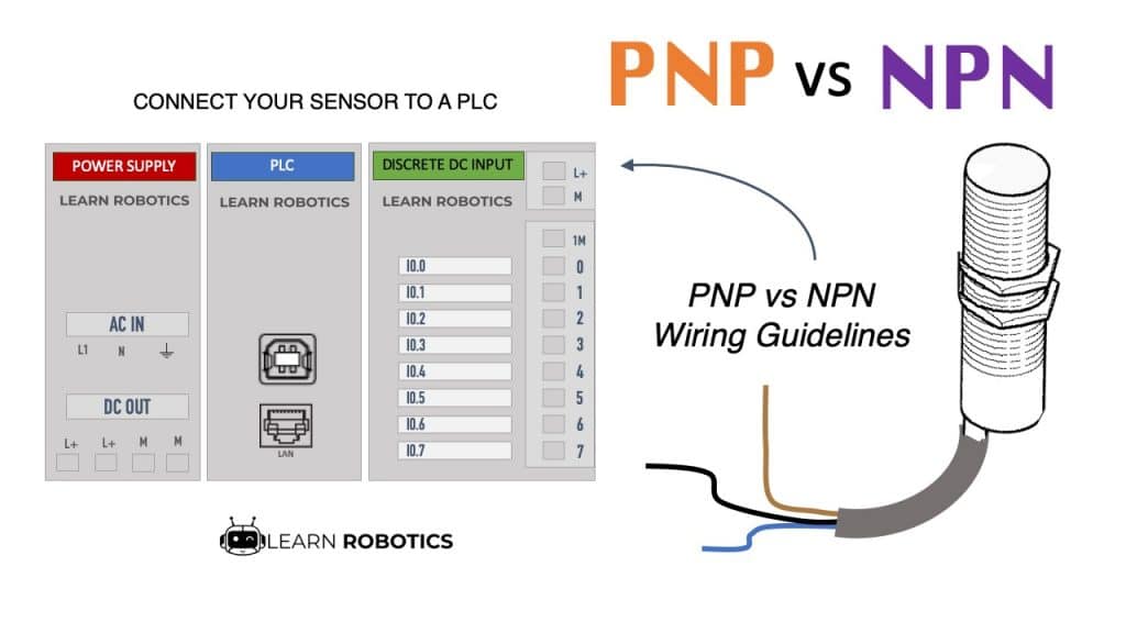
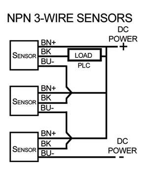
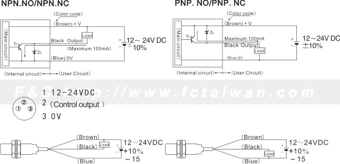
Npn proximity sensor wiring diagram. Wiring diagrams show the hook up offour sensors with npn and pnp outputs. In this video i demonstrate an npn inductive proximity sensor circuit. Photoelectric sensor works on ir principle and this sensor has 4 wireno and nc in sensor has also been explained4 wire sensor has both no and nc operating mode in it. 3 wire and 4 wire dc. Classification by output circuit. In our case the plc input will be our load.
This classification is based on the type of output circuit and the output voltage. When connecting to the plc the plc input acts as the load. Industrial sensors of all types have connection diagrams. The box in the diagram represents the load. Inductive proximity sensor cutaway with annotation. Heres a simple way remember how to wire up a 3 wire dc pnp or npn sensor.
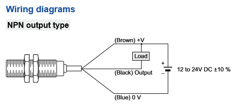
The following is a wiring diagram of an open collector npn sensor. When an object is placed near the sensor the output device turns on. Either the load is connected to negative and the positive is switched pnp continue reading an easy way to remember pnp and npn sensor. Here is a wiring diagram of an npn sensor. Pnp switched positive npn switched negative switched refers to which side of the controlled load relay small indicator plc input is being switched electrically. This sensor is the ck1 00 2h capacitive proximity sensor.
Gallery of Npn Proximity Sensor Wiring Diagram