Wiring a 3way and 4way occupancy sensor. By hubbell control solutions.
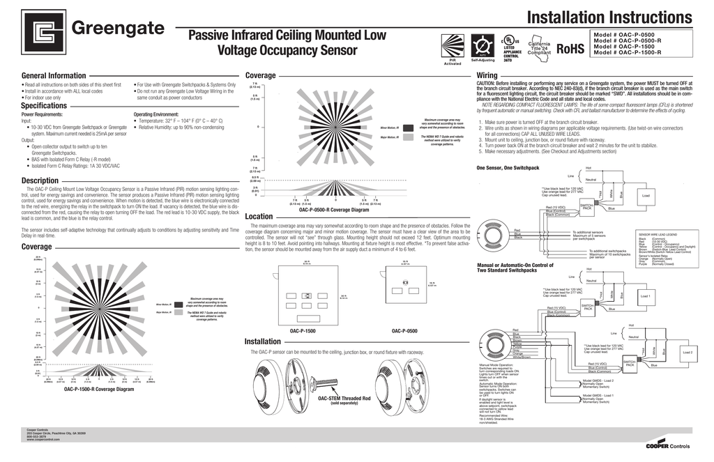
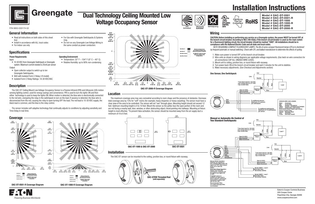
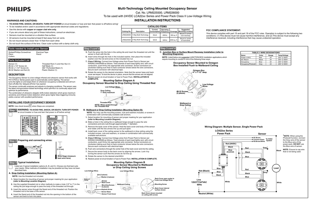
Installation Instructions
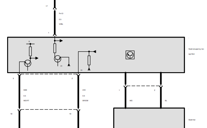
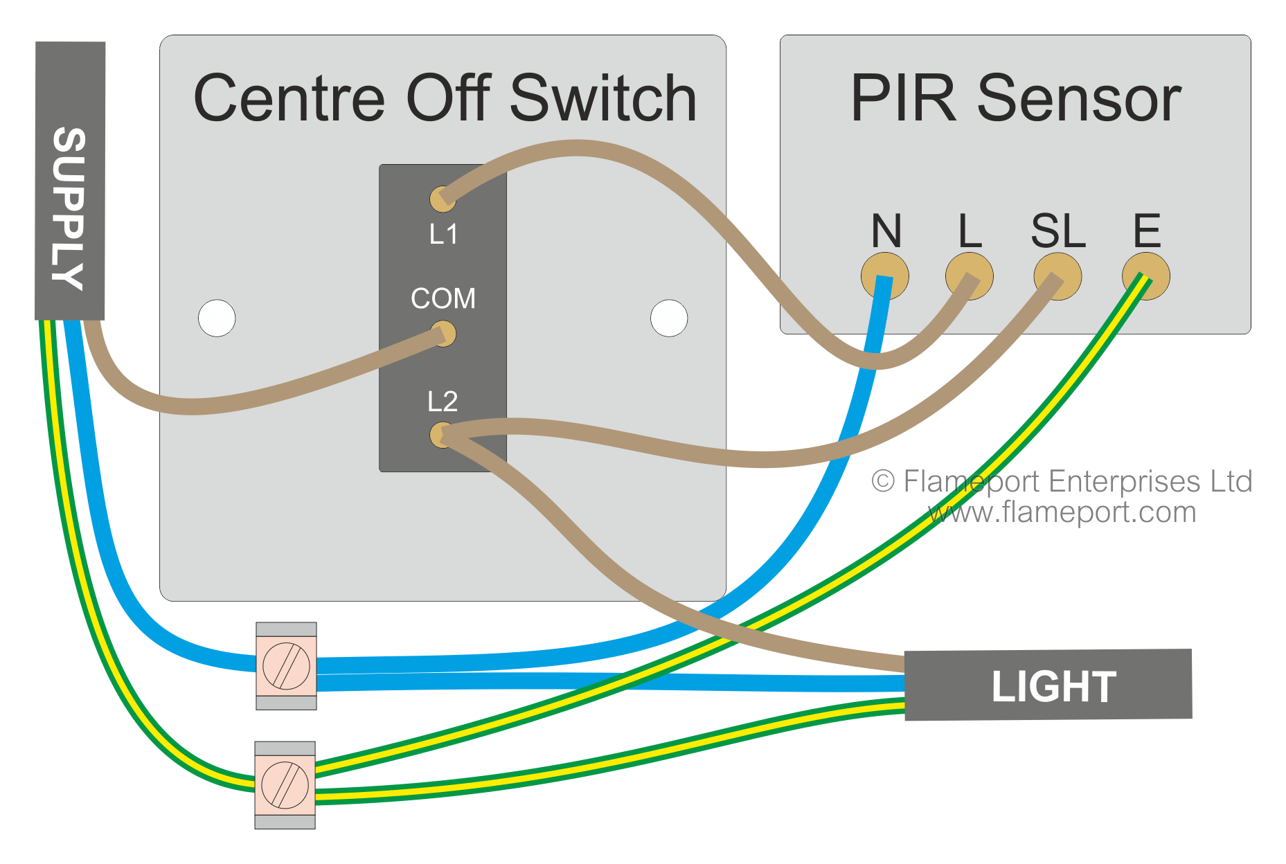
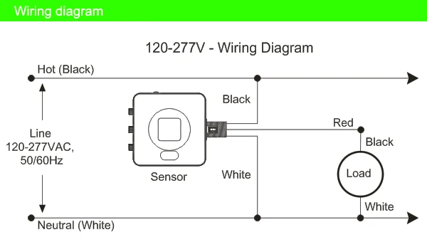
Occupancy sensor wiring diagram. Occupancy sensor switch wires each have two black wires or one black and one red and ground green. Maestro occupancyvacancy sensors dimmers switches maestro occupancyvacancy sensors sensors maestro timer. It shows the parts of the circuit as streamlined forms and the power and also signal links in between the tools. It shows the components of the circuit as simplified forms and also the power and signal links in between the tools. Consider installing 3 way occupancy sensor switches that have a wide angle coverage and variable time delays. A first consider a circuit layout may be complex however if you could review a subway map you could review schematics.
Nova t dimmer. Red wire 24vdc from power pack to the 24v terminal on the sensor. Black wire return from power pack to common terminal on the sensor. Search the lutron archive of wiring diagrams. Assortment of ceiling mount occupancy sensor wiring diagram. Refer to the wiring diagram on the next page for the following procedures.
A wiring diagram is a simplified standard photographic representation of an electrical circuit. To find a diagram for a specific product or system please use the drop down menus below. When using more sensors than this multiple power packs are required. These 3 way occupancy sensor switches may replace the existing 3 way switches. Literally a circuit is the course that permits power to flow. A wiring diagram is a simplified conventional photographic depiction of an electric circuit.
Each black wire can be a line or a load. Install a 4 way occupancy sensor to replace the existing 4 way switch. Omni low voltage acoustic and pir ceiling sensor. Ceiling mount occupancy sensor wiring diagram a novice s overview to circuit diagrams. Assortment of lutron occupancy sensor wiring diagram. Specify the product or system.
A wiring diagram is a streamlined standard pictorial representation of an electrical circuit. Occupancy sensor power pack wiring diagram wiring diagram is a simplified usual pictorial representation of an electrical circuitit shows the components of the circuit as simplified shapes and the capability and signal connections amongst the devices. Hi craig you have asked a great question. One of the black line wires connects to line voltage from the panel the other black or red load wire connects to the light s. It reveals the elements of the circuit as streamlined shapes and also the power as well as signal connections in between the devices. By headcontrolsystem variety of lutron occupancy sensor wiring diagram.
Occupancy sensor wiring diagram 1. Getting from point a to point b. Connect the low voltage. Omni dual technology acoustic and passive infrared ceiling sensor featuring intellidapt.
Gallery of Occupancy Sensor Wiring Diagram