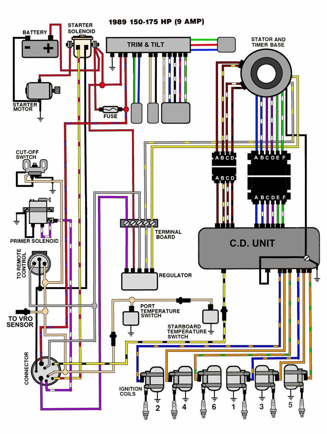
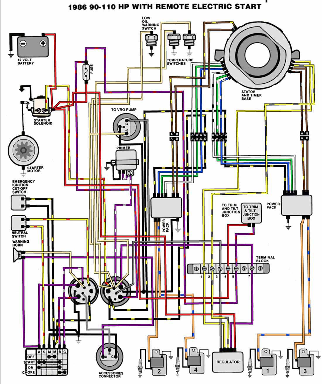
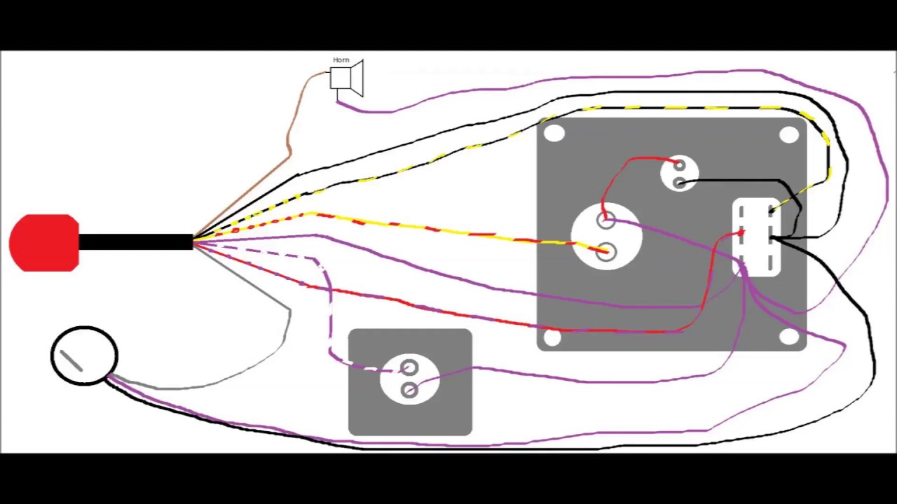
Stator to regulator charging circuit yellow with red stripe. Outboard wiring diagrams these diagrams are accurate to the best of our knowledge.

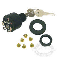
Seadog Omc Push To Choke Ignition Starter Switch Line
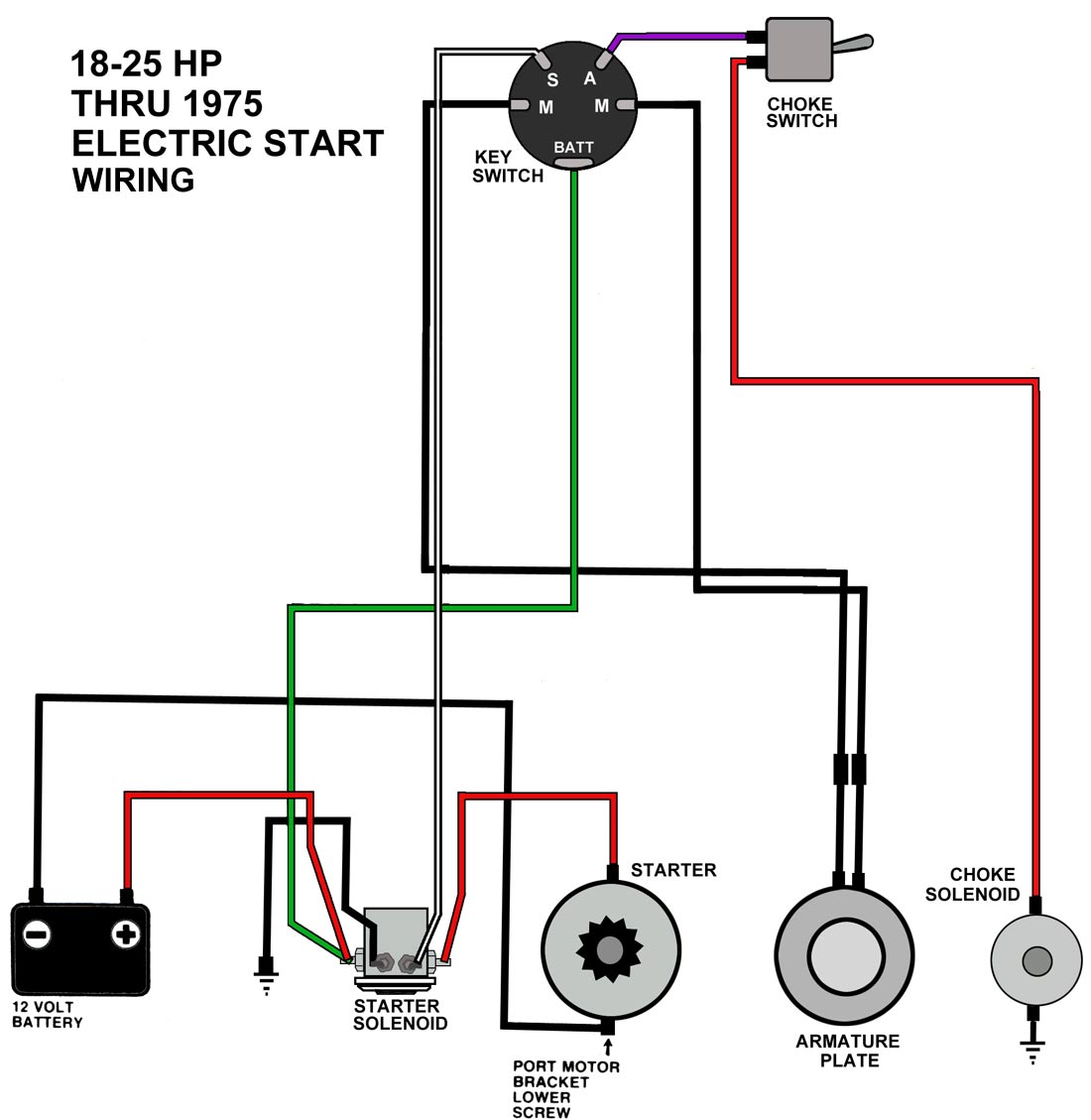
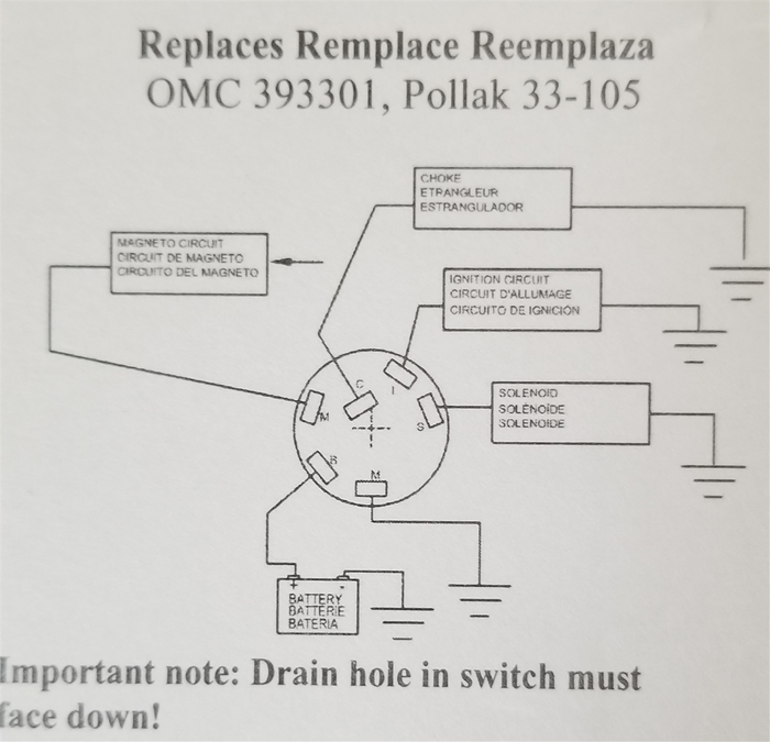
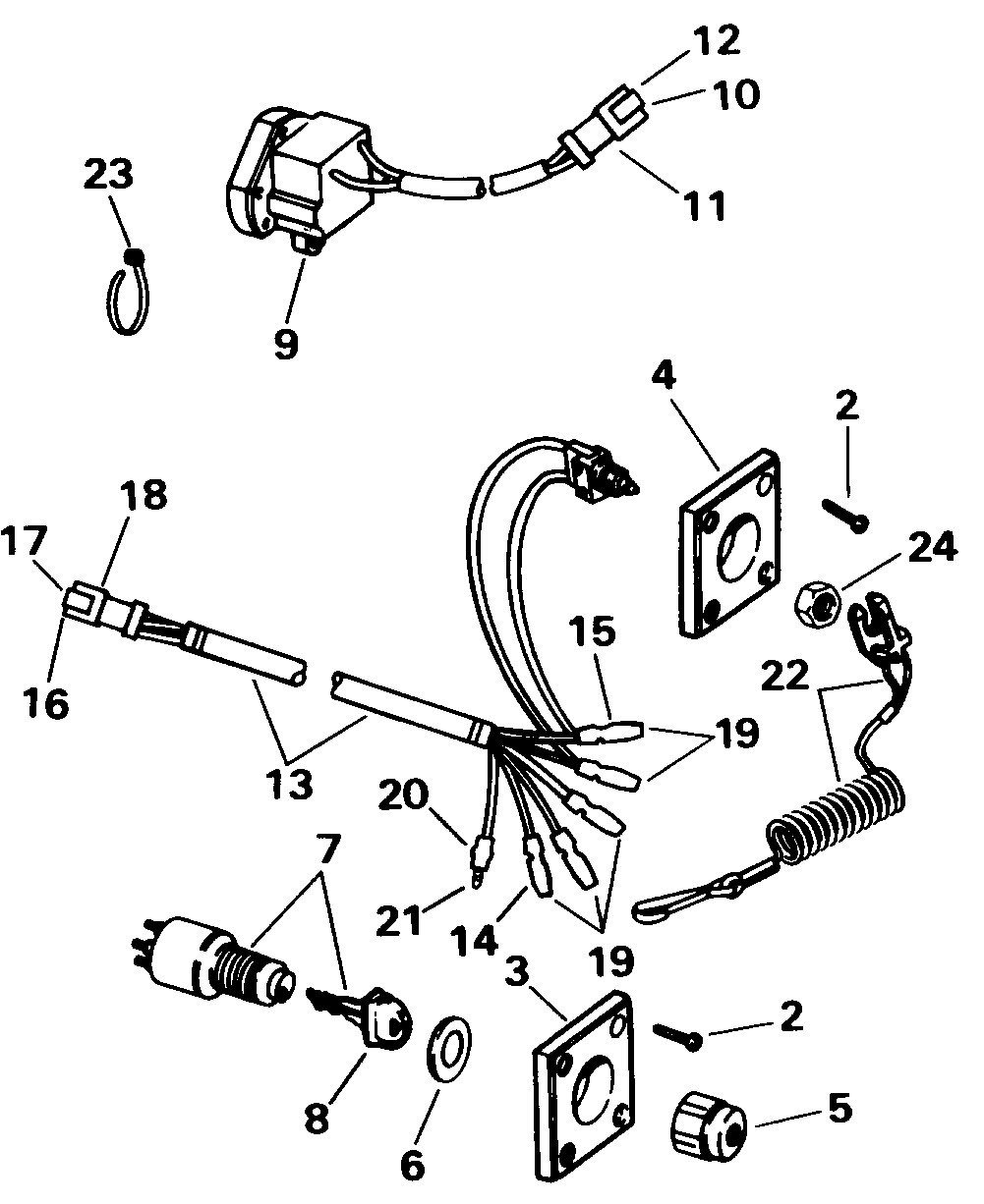
Omc push to choke ignition switch wiring diagram. V 4 motors 1982 1984. Yellow andor yellow w gray stripe. Temperature switch to warning horn andor temperature sender to temperature gauge. Offering discount prices on oem johnsonevinrude omc parts for over 50 years. Tan with or without stripes. The lettering on the switch for the wiring placement also required a magnifying tool to see.
The switch configuration and wiring is fairly standardized. Click on the image to enlarge and then save it to your computer by right clicking on the image. Find ignition switch with key and lanyard 5005801 here. 5 in stock ships immediately. Collection of johnson outboard ignition switch wiring diagram. V 4 motors 1973 76 cd ignition.
Ignition switch to neutral start switch. It shows the components of the circuit as streamlined forms and the power and also signal links in between the tools. The ignition switch on most outboard motors is operated by a key much like used traditionally in vehicles. Rated 4 out of 5 by dave san from i would buy this ignition switch again the wiring instructions that come with the switch are very hard to see. V 4 85 hp motors 1969 70 walternator. Un fused wire from battery.
Collection of mercury outboard ignition switch wiring diagram. Most outboard motors are operated and started using a key ignition switch. This description is specific to omc outboard motors but will be typical of most. However variations can exist such as between remote control and tiller models. Mercury outboard wiring harness diagram download omc outboard wiring harness diagram wiring diagram for light switch evinrude ignition switch wiring diagram fresh mercury outboard. Ignition switch to 12 volt positive.
A wiring diagram is a simplified standard pictorial representation of an electrical circuit.
Gallery of Omc Push To Choke Ignition Switch Wiring Diagram