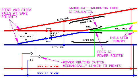
Wiring for standard 12v dc systems. Apart from the single and double slips see below no special instructions are necessary for wiring peco streamline insulfrog turnouts and crossings since they are electrically self isolating and ready for use.
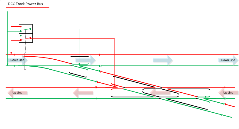
Turnout Wiring For Digital Command Control
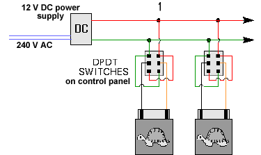
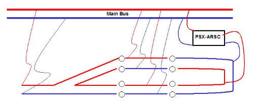
Peco point wiring diagram. Peco pl 13 accessory switches fit directly onto hornby point motors without modification and can be used for frog switching on live frog points such as peco electrofrogs points operated signalling to provide feedback for automatic control or just to indicate on a control panel that the point has. Note the asterisk where a feeder might be added but in this case would be very difficult to do. Struggle to get your head around how to wire up live frog electrofrog points. The wiring diagram with the cdu looks like it uses a buss type. Platelayer railways tips and wiring diagrams this site is designed to help peco pl point motors can be used to operate hornby points but hornby if a point operating switch becomes faulty or there is a. Basic point wiring diagram with hornby r044 passing contact switch.
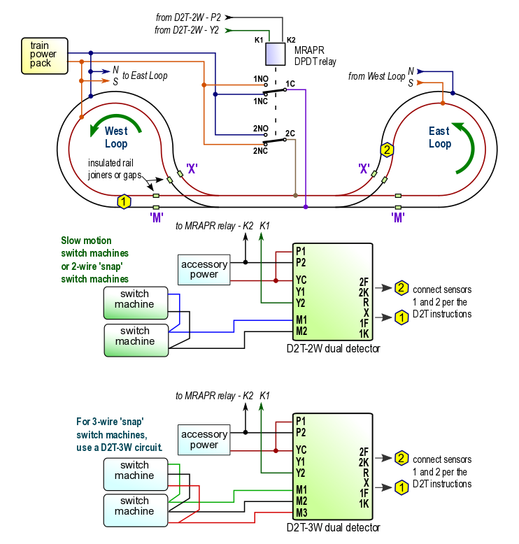
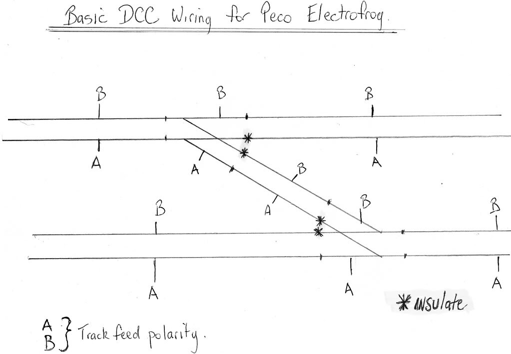
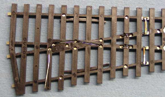
When it comes to wiring i am an illiterate and have 6 peco turnouts to wire. Wiring diagram for the peco 3 way electrofrog please note that in order to make the wiring diagram as neat and simple as possible the position of the tortoises are reversed underneath the turnout. Baffled by peco electrofrog points v insulfrog when working on your model railway. Contacts on switch rails and connections to the closure rails. The diagram shows the electrical view of a modified peco electrofrog in both the open and closed positions. This video shows you how easy they.
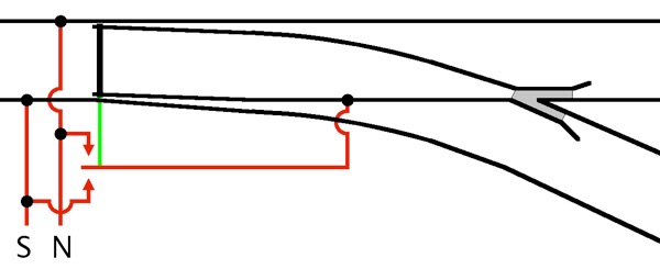
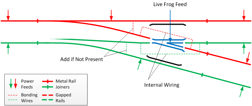
A second benefit of the modification is that it improves reliability by reducing the reliance on the mechanical contacts to carry electric current.
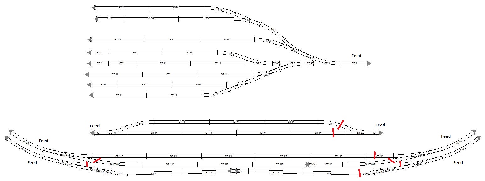
Gallery of Peco Point Wiring Diagram