Cat6 cabling should be used where throughput of greater than 100mbps is desired. There are two ways of filtering the phone signals in a dsl setting.

Tt 0161 Home Data Wiring Diagrams Download Diagram
Phone jack wiring diagram dsl. Variety of centurylink dsl wiring diagram. A circuit is generally composed by several components. Its cheaper to do the wiring yourself and its not difficult. Another thing which you will come across a circuit diagram could be traces. Each workstation where you will be installing a voip phone must have category 5 cat5 category 5 enhanced cat5e or category 6 cat6 cabling installed with an ethernet rj45 jack. It shows the elements of the circuit as streamlined forms and the power as well as signal connections in between the devices.
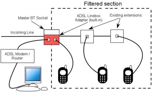
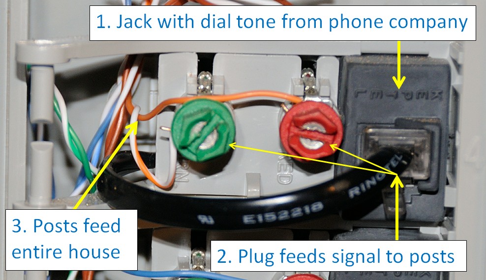
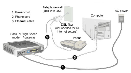
Variety of centurylink dsl wiring diagram. Regular telephone wire cat3 and rj11 jacks do not support voip. An alternative would be to build one filter like the one shown here. A wiring diagram is a streamlined conventional pictorial representation of an electric circuit. A splitter is the preferred option by most alarm system companies. The first is to install a dsl filter at each telephone.
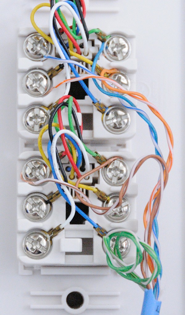
There are two things which are going to be found in any dsl phone jack wiring diagram. Centurylink dsl wiring diagram gallery. Each filter is just a little module with a very short cable. Category cable works just as well as the old cable for phone service and it works much better for data such as for a dsl internet connection. Dsl phone jack wiring diagram wiring diagram is a simplified pleasing pictorial representation of an electrical circuit. The first element is emblem that indicate electrical component from the circuit.
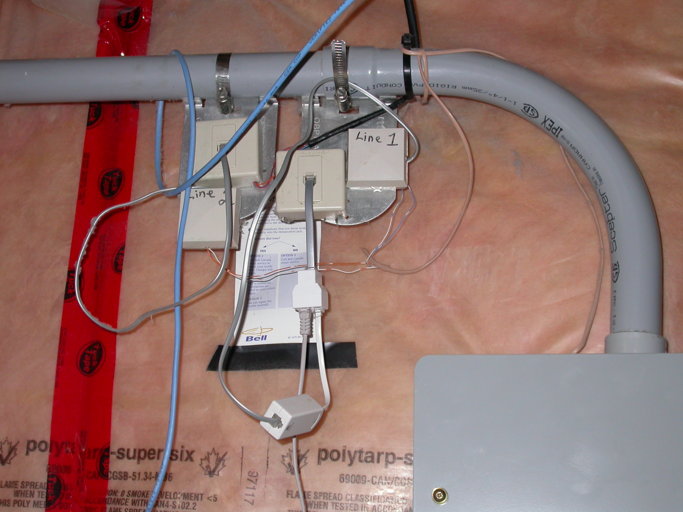
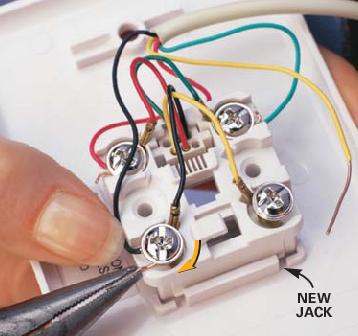
Adsl home wiring diagram save dsl phone jack wiring diagram. Dsl subscribers may expect a phone company to install appropriate jacks in their household but this is not a requirement. You plug the filter into the jack and then plug the phone into the filter. With either type of cable once the cable is run to the jack location wiring the jack is a simple matter of matching up the correct wire colors. It shows the components of the circuit as simplified shapes and the aptitude and signal links between the devices. An alarm system will require either a special filter for the connection to the rj 31x jack for the alarm system or a splitter to separate the dsl service from the telephone line before it goes to the rj 31x jack for the alarm system.
A wiring diagram is a simplified conventional photographic representation of an electrical circuit. Phone lines consist of four strand wires including two transmit and two receive frequencies. It reveals the parts of the circuit as streamlined forms and also the.
Gallery of Phone Jack Wiring Diagram Dsl


/Phonejack-GettyImages-sb10069937br-001-d954796fd0c34cf19d36499618f9b936.jpg)