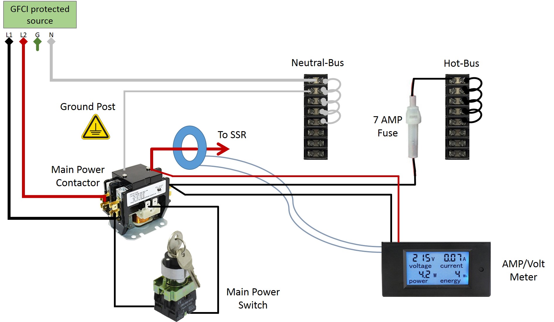
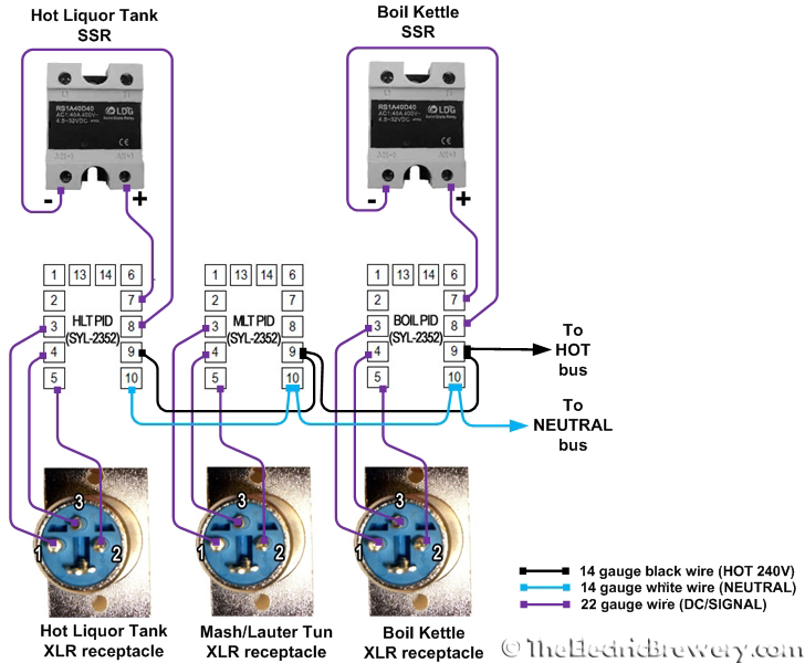
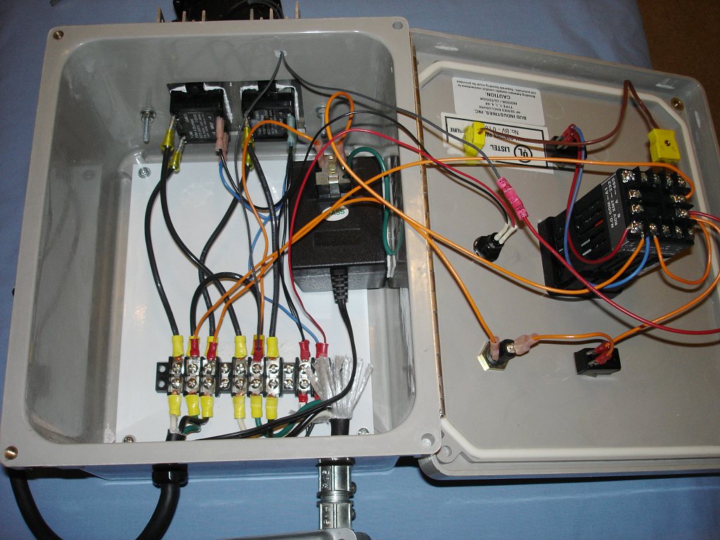
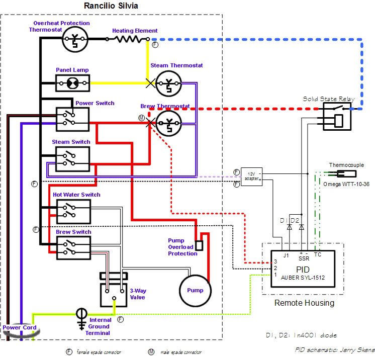
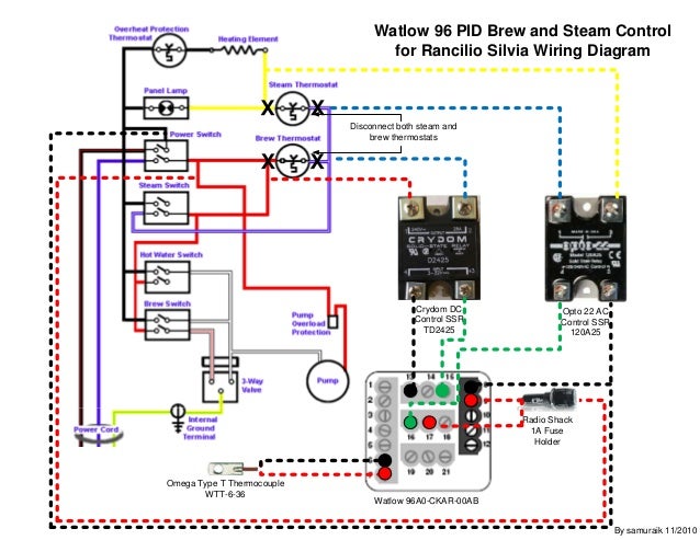
The block diagram on the right shows the principles of how these terms are generated and applied. In the case of the pid controllers you can see in the wiring photo that ive daisy chained the hot and neutral wires at the spade lugs to cut down on wires.

I Need A Single Pid Single Element Diagram Homebrewtalk
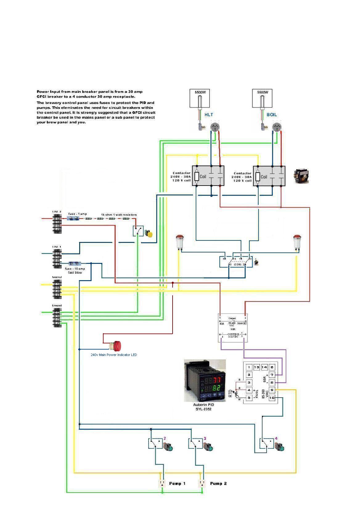
Pid controller wiring diagram. This one cost me about 16. The distinguishing feature of the pid controller is the ability to use the three control terms of proportional integral and derivative influence on the controller output to apply accurate and optimal control. Wiring the inkbird itc106 vh pid controller duration. A wiring diagram is a simplified standard photographic representation of an electric circuit. Visit us on face book and subscribe to this page. Since the wiring will depend on the type of thermocouple pid controller heating element you use.
Some pid controllers can switch high power heaters directly others will need solid state relays. They can be found on google and are relatively inexpensive. So if i. Please use caution when wiring your own pid controller. Main control pid or onoff output time proportioning a proportional band 0 to 400 oc programmable cycle time. Collection of temperature controller wiring diagram.
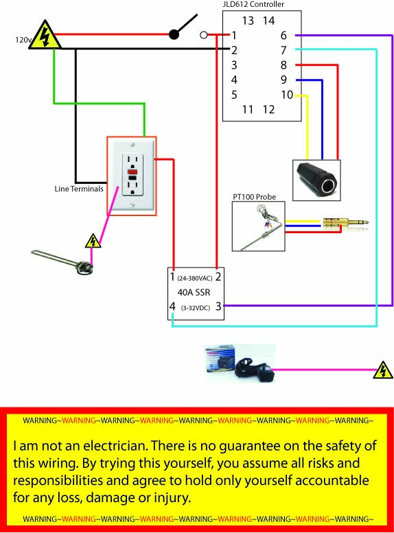
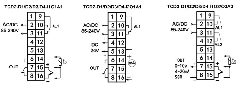
Wellborn collection of pid temperature controller wiring diagram. It reveals the components of the circuit as streamlined shapes and the power and also signal connections in between the devices. If you are using a 3 wire sensor then it connects to terminals 3 4 and 5. April 25 2020 by larry a. How to wire a inkbird itc 1000 for use in a keezer bonus wiring diagram included. Its just sitting there in the diagram relaying the temperature of the mash.
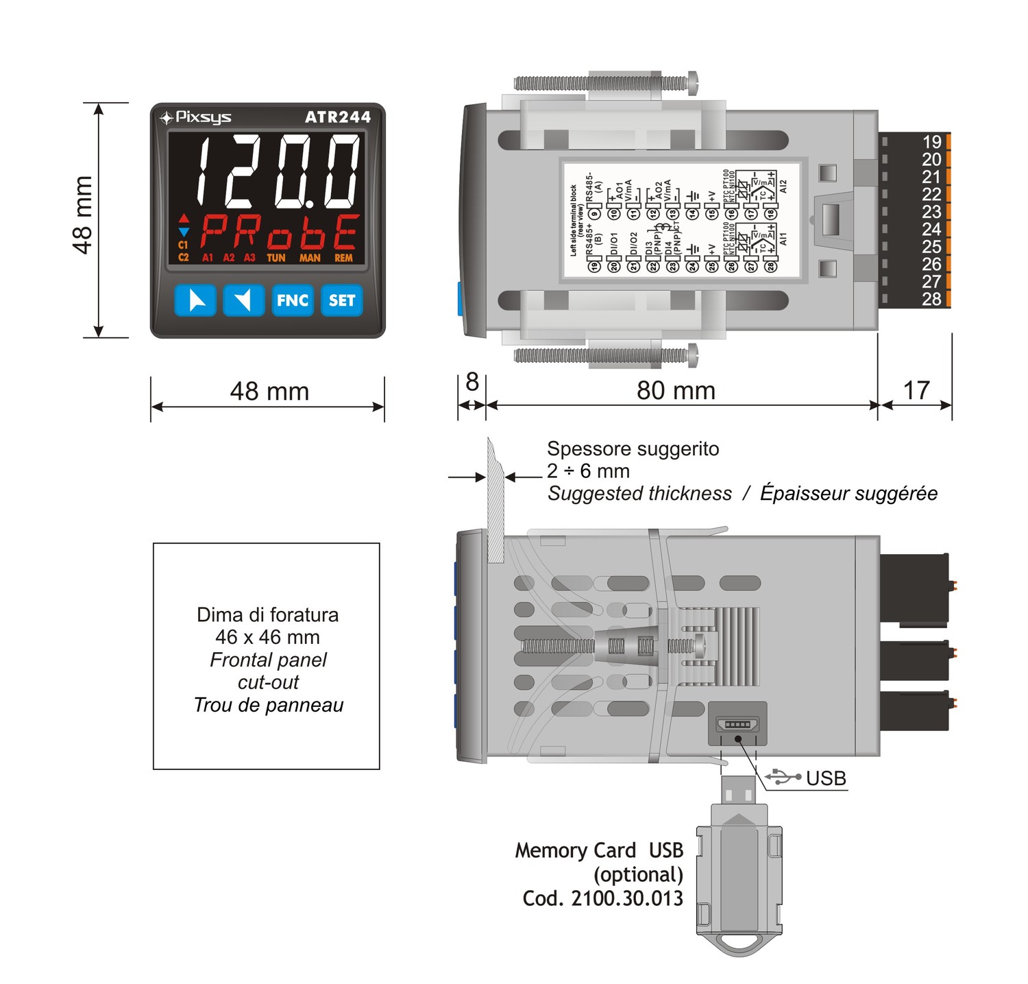
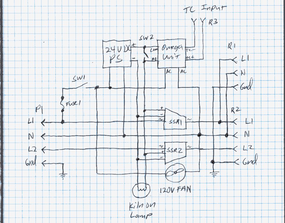
Then you have the mash pid according to the diagram and the part list there isnt an ssr for it. A wiring diagram is a simplified traditional pictorial representation of an electrical circuit. If you know how to translate it wiring everything up is quite simple. Barley and hops brewing 23368 views. In the instruction manual for your pid and possibly on a sticker on the case will be a wiring diagram like the one above. It reveals the elements of the circuit as streamlined forms and also the power and also signal links between the tools.
Lets start with the temperature sensor. Automanual 01 to 999 sec programmable b onoff control hysteresis from 01 to 999oc auto tune via keys on front panel accuracy 025 of full scale 1oc whichever is greater set point limit.
Gallery of Pid Controller Wiring Diagram