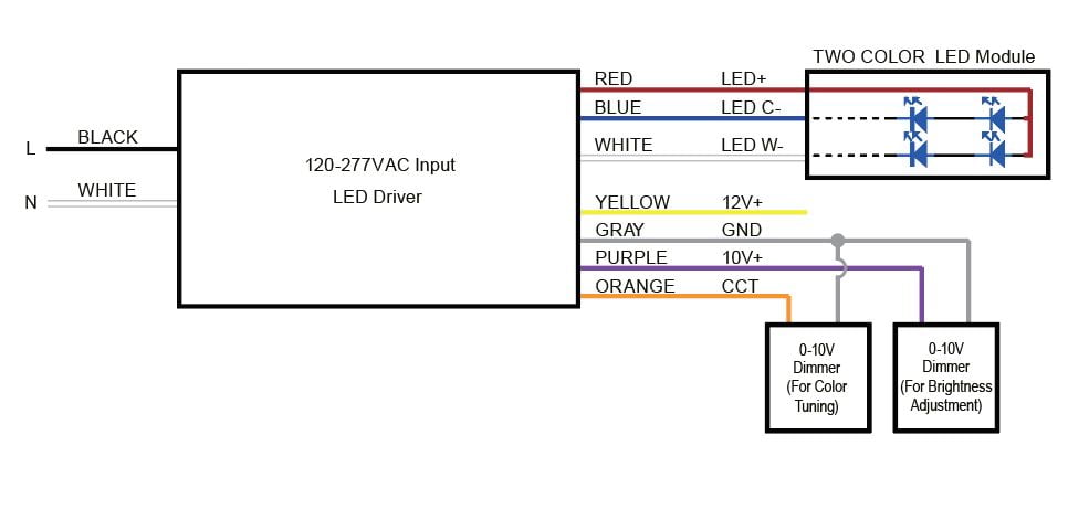
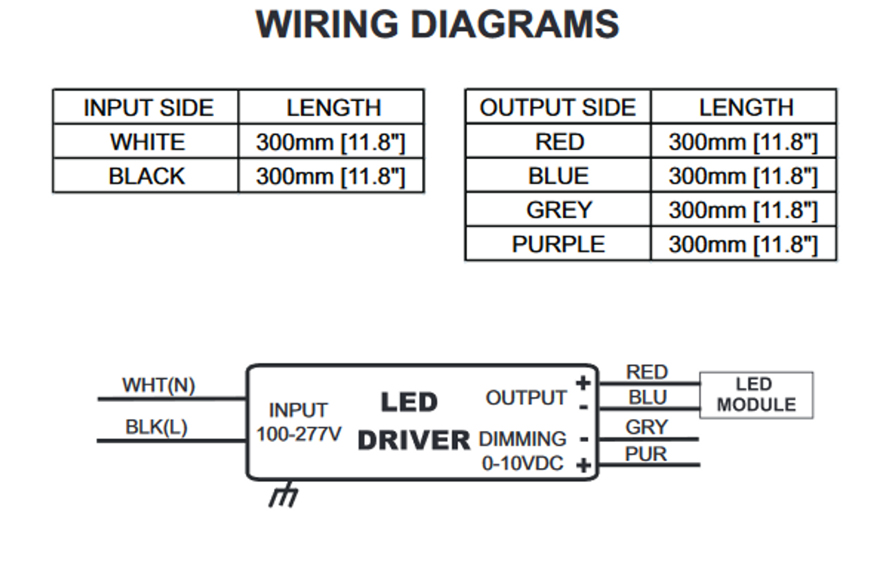
A wiring diagram is a simplified traditional photographic representation of an electrical circuit. Make sure all connections are in accordance with the national electrical code and any local regulations.

Ams 48 2000 N D0114354 055 00 Pdf Document
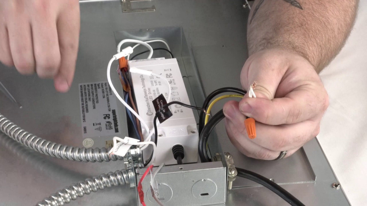
Pld10 emergency led driver wiring diagram. Select correct wiring diagram to connect the emergency driver to the led load ac led driver and switch. When either one of the switches. Select correct wiring diagram to connect the emergency driver to the led load ac led driver and switch. The dual lite pld10 are universal input 120 277v emergency led battery packs that work with an ac led driver to allow an led lighting load to be used in both normal and emergency operation. Install in a visible location the labels caution status see illustration 4 led led. It reveals the parts of the circuit as simplified shapes and also the power and signal connections in between the tools.
Provides a minimum of 90 minutes of emergency lighting. Bi level switch dimming drivers have two hot leads and a single neutral lead for input power connections. The following wiring diagrams are only applicable to everline led drivers that incorporate switch dimming control capabilities when connected with the bodine bsl17c c2 and bsl310 emergency led drivers. The dual lite pld10m are universal input 120 277v emergency led battery packs that work with an ac led driver to allow an led lighting load to be used in both normal and emergency operation. Provides a minimum of 90 minutes of emergency lighting. Install the labels caution status in a visible location see illustration 4.
Make sure all connections are in accordance with the national electrical code and any local regulations. Variety of led driver wiring diagram.
Gallery of Pld10 Emergency Led Driver Wiring Diagram