Data link connector circuit. Power door lock wiring diagram you will want a comprehensive professional and easy to know wiring diagram.
2010 Super Crew Door Lock Wiring Issue Ford F150 Forum
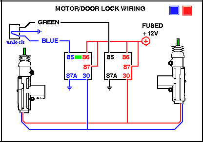
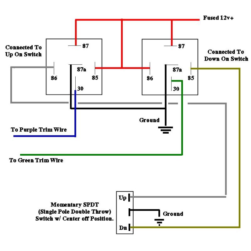
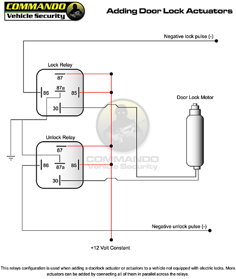
Power door lock wiring diagram. In most cases you will not need to add relays for this type. Chexit wiring diagram. The relay and wiring are shown in the diagram above. Heater circuit anti lock brakes. Most of the newer alarms and keyless entries on the market today have both positive and negative 200 ma door lock outputs that are usually capable of activating the factory relays. Single wire door lock systems type f type g type h there may be one two or three wires in the harness not counting the illumination wires if any and only changes in voltage and or resistance on one wire to lock and unlock.
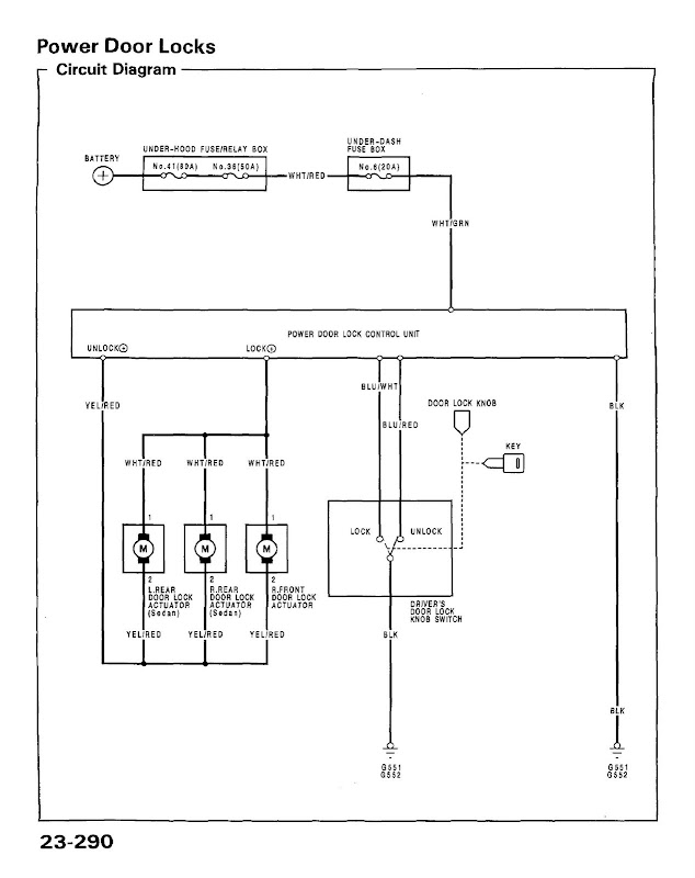
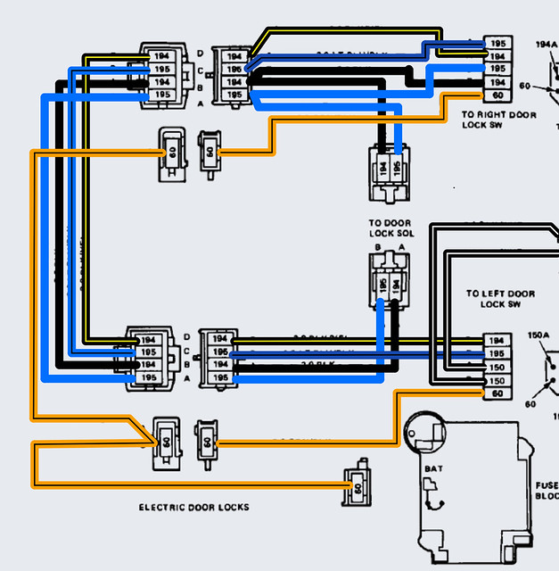
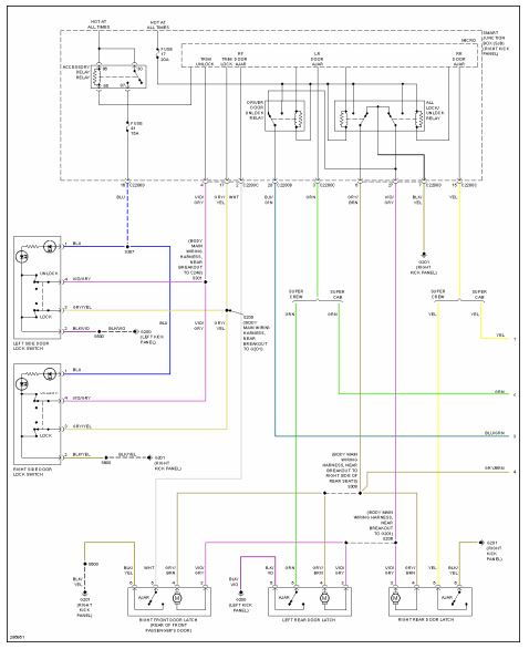
1995 system wiring diagrams chevrolet tahoe air conditioning ac circuit. Anti lock brake circuits computer data lines. The tan and gray wire pairs in each door are the door lock motors actuators. Keyless entry circuit 4 door power mirrors. With this sort of an illustrative manual you will have the ability to troubleshoot avoid and total your tasks without difficulty. Steelcraft order form.
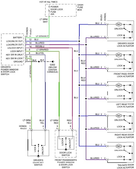
Lever locks for fire doors. Some of these will open a circuit to lock and ground a wire to unlock. Advanced power door lock management is a necessity now given todays complex automotive systems. The need to reduce vehicle weight has prompted these more complex module driven door lock circuits. Type a and type b are the most common types of door lock switch configurations found in most vehicles. Keyless entry circuit 2 door.
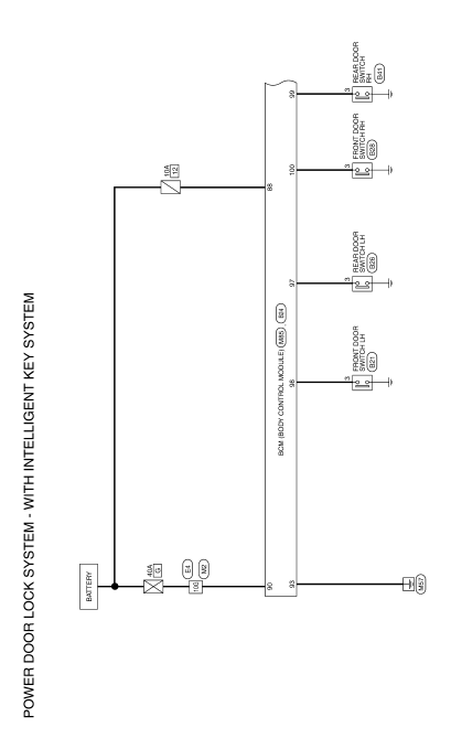
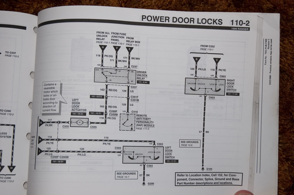
Door lock circuit 4 door. Autozone repair guide for your wiring diagrams power door locks 2002 power door lock system wiring diagram. Wiring diagram quote form. What power supply needed for electric strike and auto operator. Door lock circuit 2 door. Sliding door wiring diagram.
The light blue orangeblack and blackwhite wires connect to the door lock switches orangeblack is battery power from the fuse block ground is supplied through the mounting of the relay to body sheetmetal. Single door controlled egress wiring diagram 01 single door digital entry wiring diagram 10 single door dk 26 with door prop alarm wiring diagram 15 single door dk1 11 xms dt 7 wiring diagram 20 single door dk 26 remote release wiring diagram 14 single door dk 26 unl 24 and dt 7 wiring diagram 18 single door dk 26 using the hard code to toggle lock off and on wiring diagram. 3 wire positive door locks. Field measurement form. Door order form. Mag lock wiring diagrams.
Gallery of Power Door Lock Wiring Diagram