Assortment of duplex pump control panel wiring diagram. Connect the wires coming from the pumps to the pump terminals.
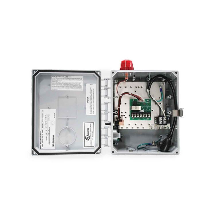
Sim A Single Phase Simplex Sump Pump Control Panel See
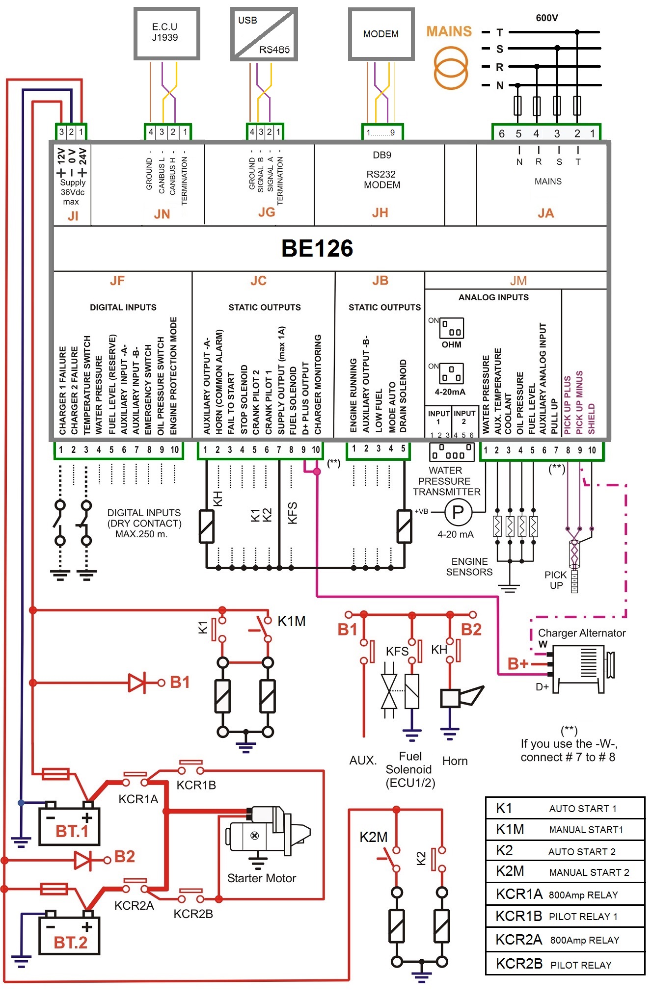
Pump control panel wiring diagram. A wiring diagram is a simplified traditional pictorial representation of an electric circuit. A wiring diagram is a simplified traditional photographic depiction of an electric circuit. December 13 2018 by larry a. Connect the wires coming from the pumps to the pump terminals. A wire set from the storage tanks pressure switch and a wire set that leads to the pump motor enters the control box. If it runs straight to the pressure switch it is a two wire.
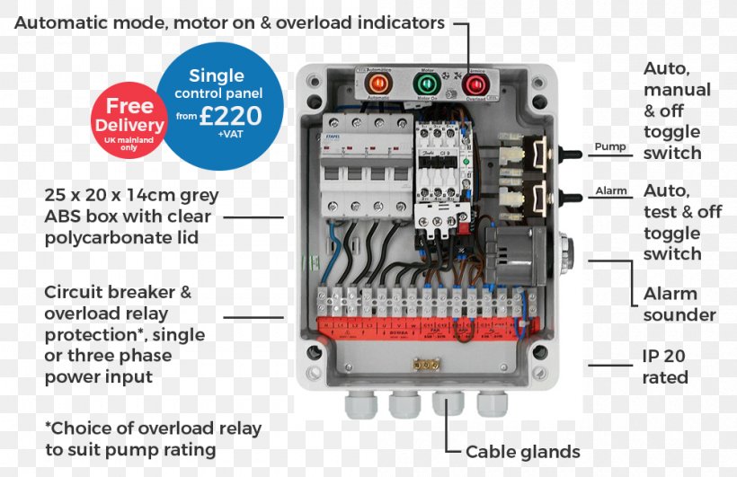
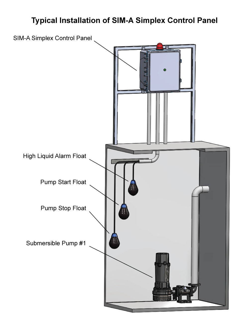
If the electrical control panel is to be set remote from the pump wet well a nema 4 junction box should be used to make the necessary power and control connections. A wiring diagram is a streamlined traditional pictorial depiction of an electric circuit. No sealing compound is necessary to make connections watertight. The keen pump nema 4 junction box is provided with compression connectors for sealing all wires. Variety of duplex pump control panel wiring diagram. A wiring diagram is a simplified traditional photographic depiction of an electrical circuit.
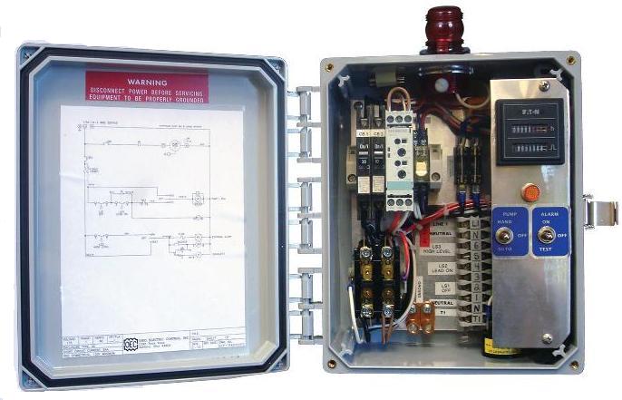
Connect the incoming power to the panel. Refer to the panel wiring diagram for the correct terminal connections for your system. The wiring connection of submersible pump control box is very simple. Connect the incoming power to the panel. A submersible pump can be either two or three wire regardless of the voltage coming from the panel so start at your pump and follow the conduit back. Assortment of pump control panel wiring diagram schematic.
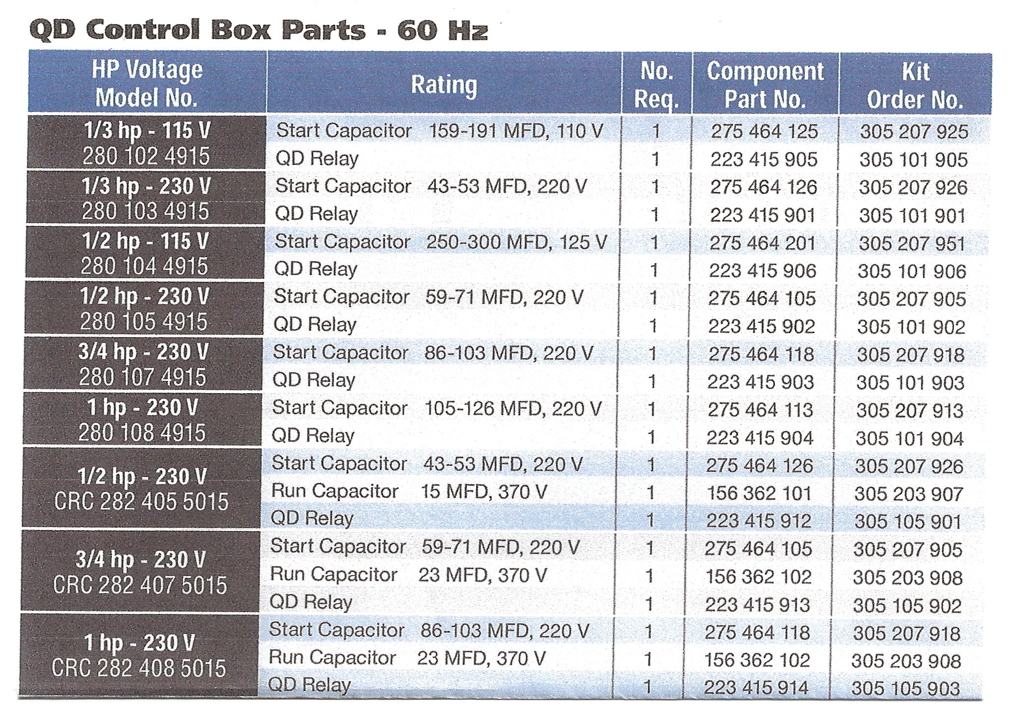
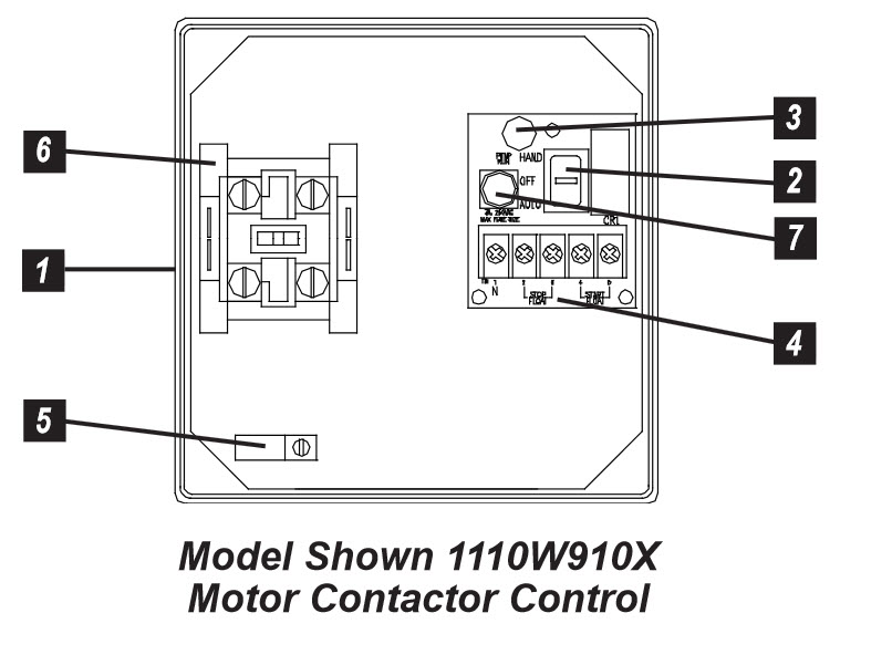
It shows the parts of the circuit as simplified shapes as well as the power as well as signal links between the devices. Here is the complete guide step by step. Collection of submersible pump control box wiring diagram. If the conduit runs into a control box before continuing to the water pressure switch chances are you have a three wire pump. It reveals the components of the circuit as streamlined shapes and also the power as well as signal links in between the gadgets. Step 3 inspect the control boxs wiring diagram located on the back of the lid.
Refer to the panel wiring diagram for the correct terminal connections for your system. Power to the panel must be appropriate to the control panel and pump motor 120 vac single phase for a 120 vac motor 240 vac single phase for a 240. It shows the elements of the circuit as streamlined forms and the power and signal connections in between the devices. Power to the panel must be appropriate to the control panel and pump motor 120 vac single phase for a 120 vac motor 240 vac single phase for a 240. Single phase submersible pump control box wiring diagram 3 wire submersible pump wiring diagram in submersible pump control box we use a capacitor a resit able thermal overload and dpst switch double pole single throw.
Gallery of Pump Control Panel Wiring Diagram