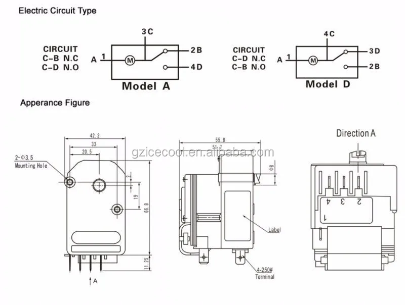
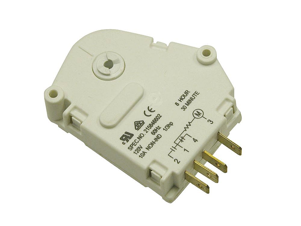
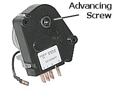
Whirlpool genuine oem w refrigerator defrost timer kit. A schematic drawing of the timer is shown in figure 282.

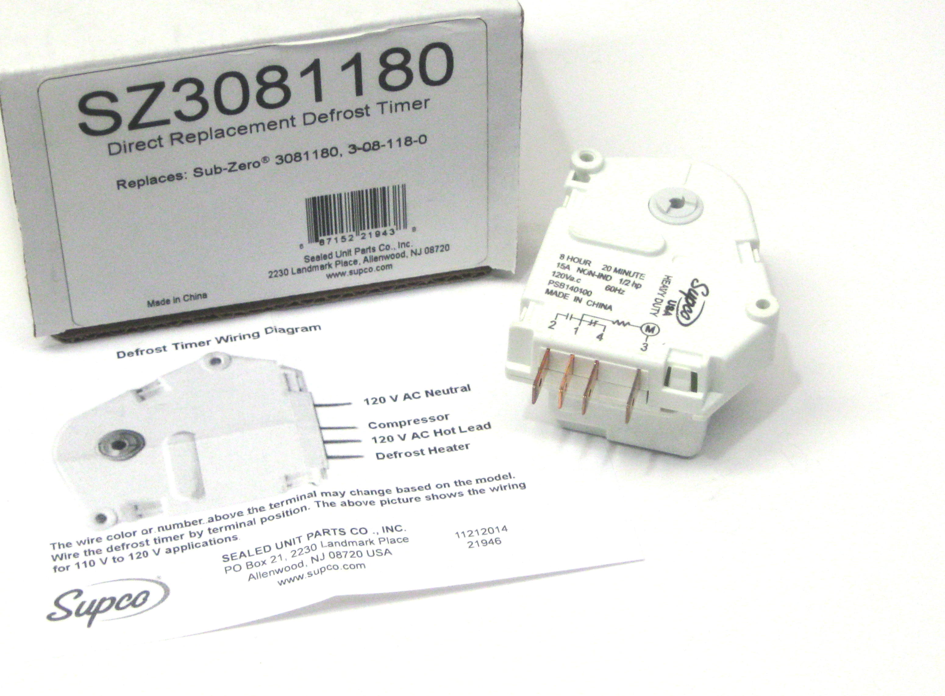
Defrost Timer Wiring Diagram Cold Room Cold Room
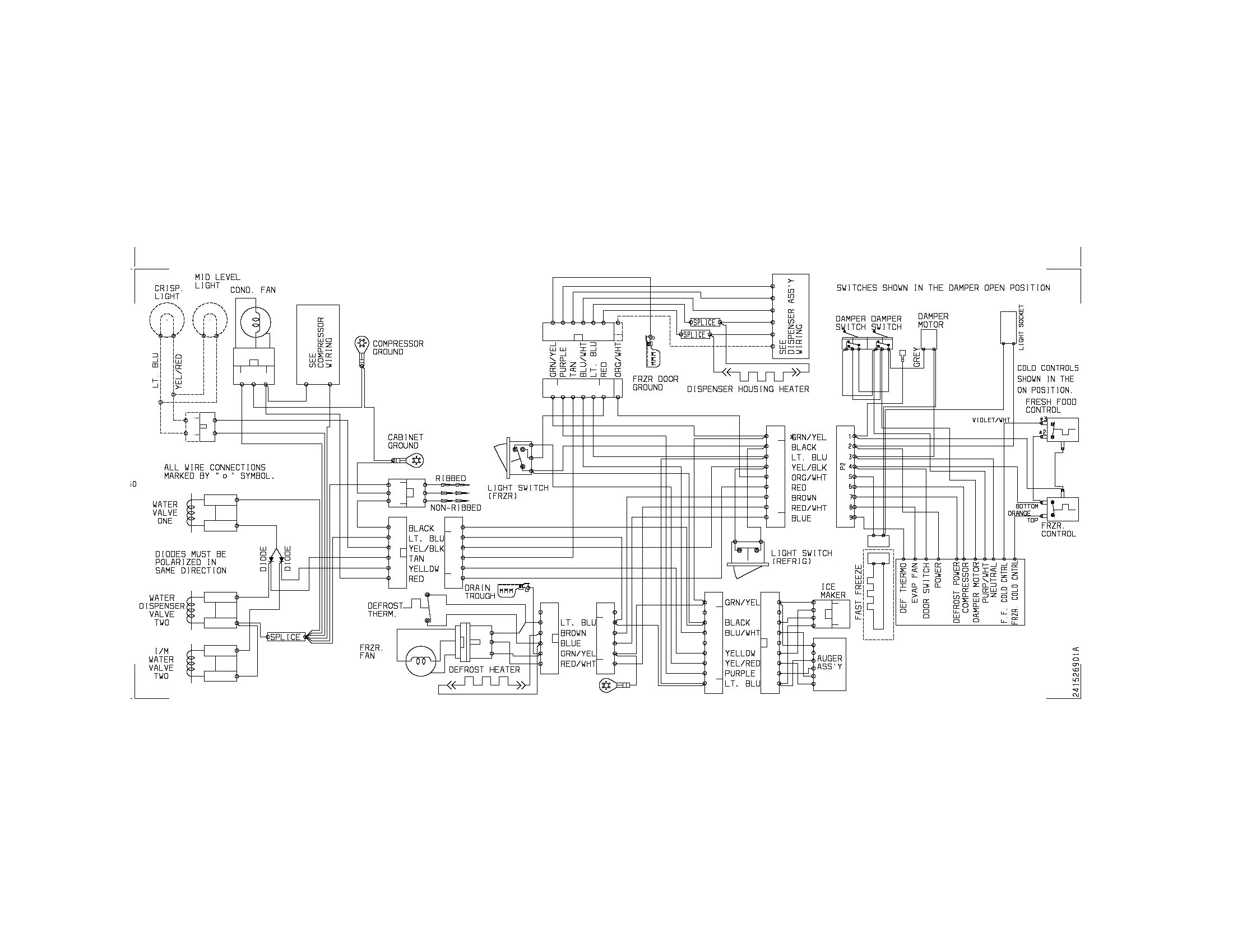
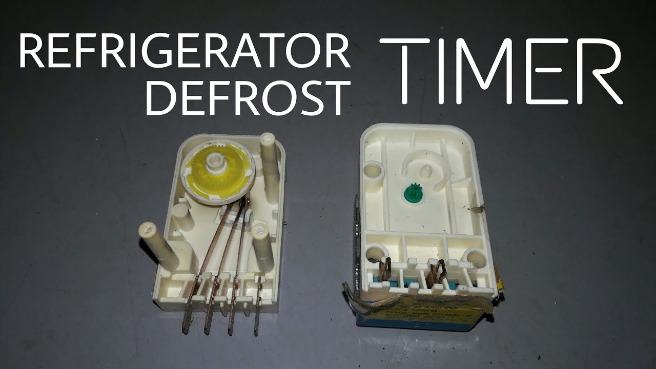
Refrigerator defrost timer wiring diagram. A wiring diagram is a streamlined standard pictorial representation of an electrical circuit. In this video you can learn about the defrost timer wiring diagram of a frost free refrigerator and circuit diagram step by step details about the function of the timer bimetal heater thermostat. Assortment of refrigerator defrost timer wiring diagram. This timer kit is designed for both. A wiring diagram is a streamlined standard pictorial depiction of an electrical circuit. Getting from factor a to point b.
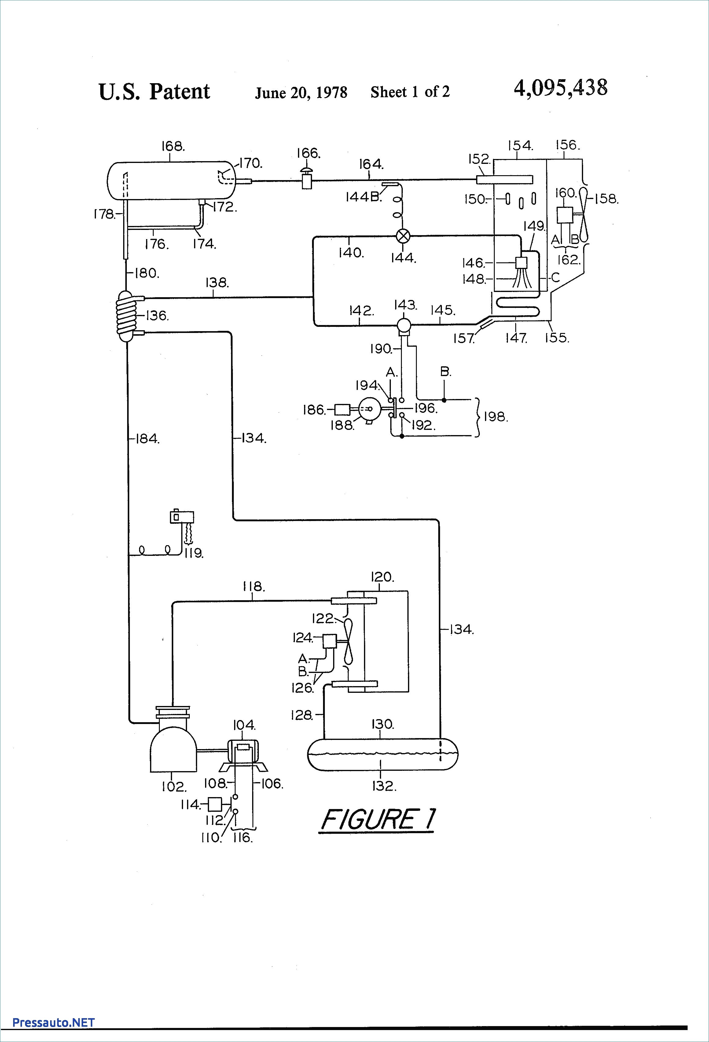
The contacts are operated by a cam that is gear driven by the clock motor. It shows the elements of the circuit as streamlined forms and also the power and also signal links in between the devices. October 18 2018 by larry a. This timer will activate for 21 minutes every 8 hours. Kenmore refrigerator defrost timer w this eight hour defrost timer so i figured my model was too old the wiring diagram was simalar to mine on. The defrost timer is operated by a single phase synchronous motor like those used to operate electric wall clocks figure 281.
Wellborn variety of walk in freezer defrost timer wiring diagram. A very first look at a circuit diagram may be confusing however if you can check out a train map you can review schematics. Literally a circuit is the path that allows electricity to circulation. Refrigerator defrost timer wiring diagram a beginner s overview of circuit diagrams. The function is the same. It shows the components of the circuit as simplified forms and also the power as well as signal connections in between the gadgets.
July 10 2018 by larry a.
Gallery of Refrigerator Defrost Timer Wiring Diagram