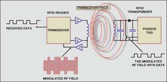
The whole system uses the passive rfid system with inductive coupling method. Please download these rfid access control wiring diagram by using the download button or right select selected image then use save image menu.
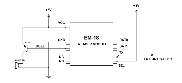
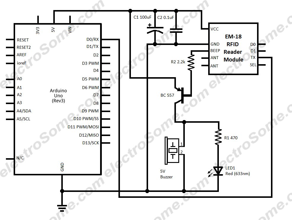
Em18 Rfid Reader Module Pinout Equivalents Circuit
Rfid wiring diagram. Rc522 rfid reader features. Often only one of the two devices needs to be powered while the other is a passive device. Wiring diagrams help technicians to find out the way the controls are wired to the system. As the rfid card tag is swiped against the rfid reader a carrier signal of 125 khz is send to the tag coil which receives this signal and modulates them. Rfid stands for radio frequency identification and it basically uses the radio waves to read the information on the tag. The only 33v is required to activate the device.
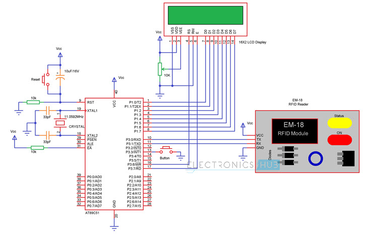
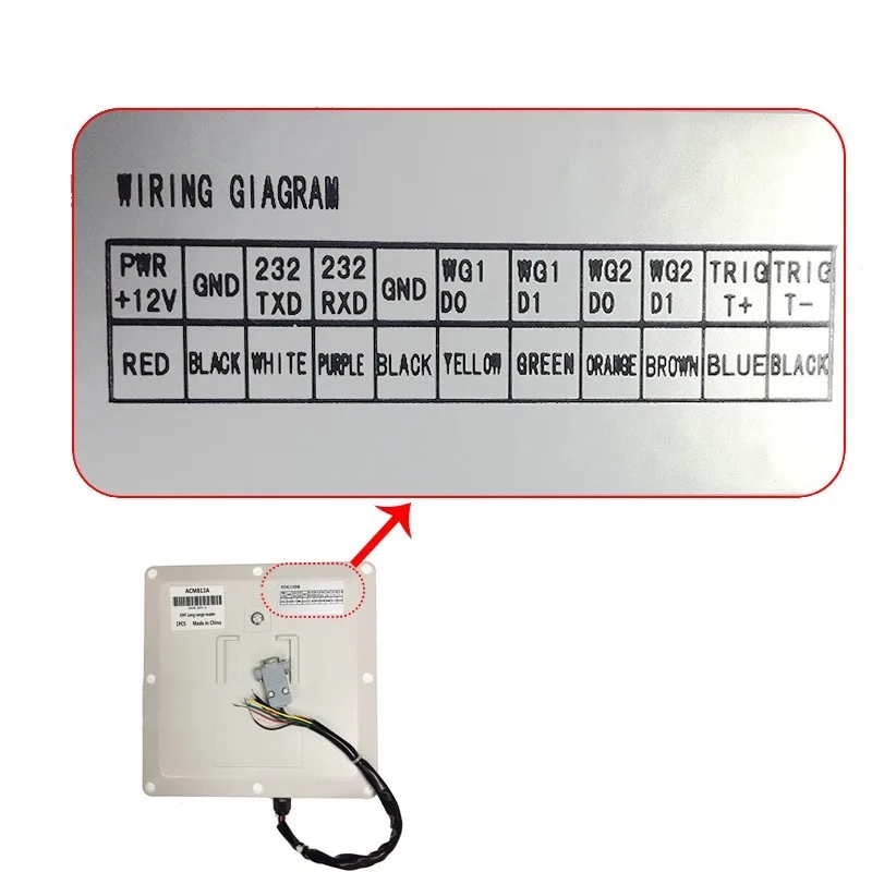
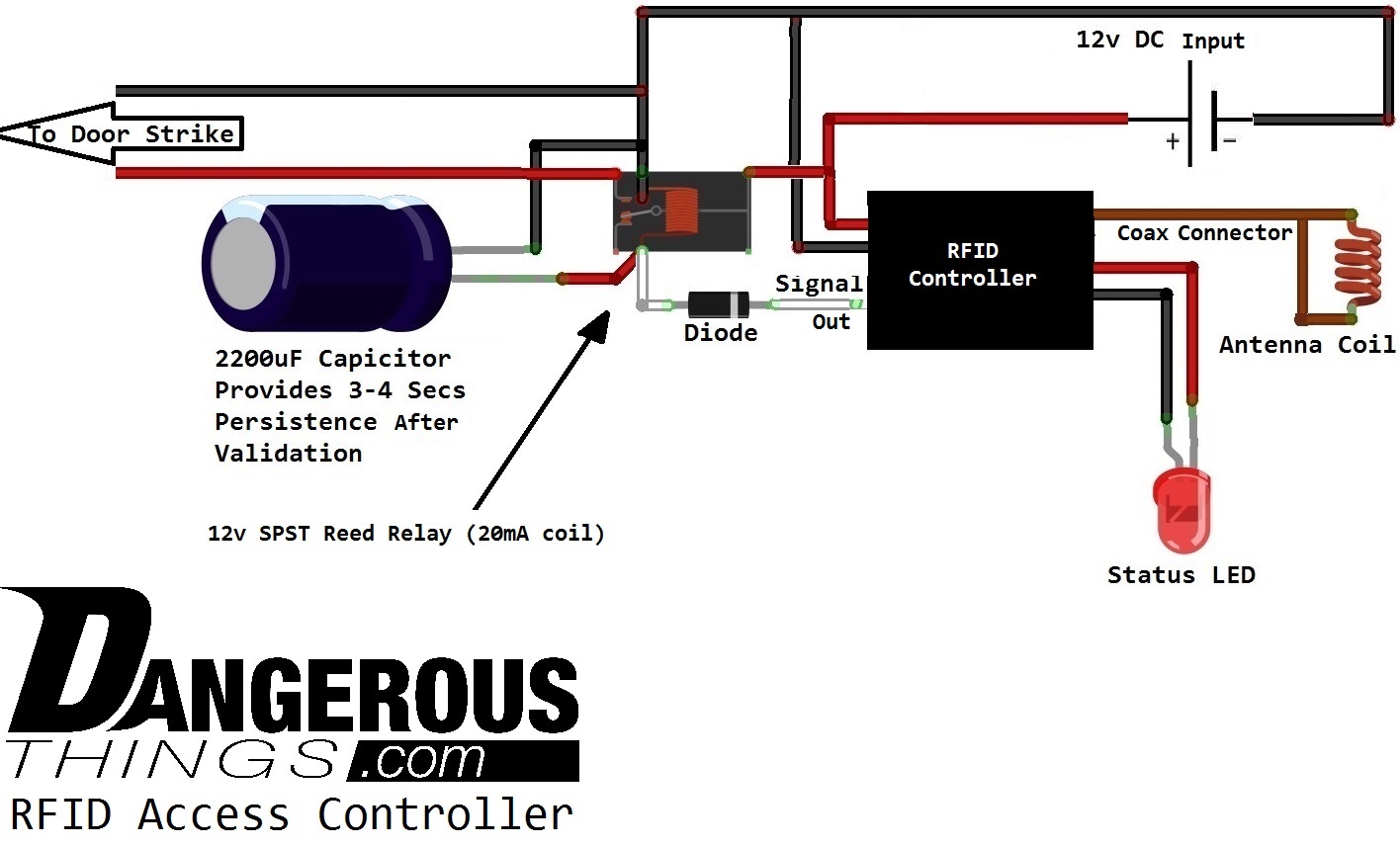
Rfid access control wiring diagram sample. Its auto sleep mode makes it less power consumption module. January 15 2019 by larry a. The module has three kinds of communications uart. The complete circuit diagram is as follows. A wiring diagram is a streamlined traditional pictorial depiction of an electrical circuit.
Rfid rc522 uses mutual induction to activate the cards and 1356mhz for data transfer. This modulated signal is received by the reader interfaced to the microcontroller. Rfid access control wiring diagram. Rfid or radio frequency identification is a system for transferring data over short distances typically less than 6 inches. Wiring and programming of rfid sensor. The rfid tags contains the embedded transmitter and receiver attached to an object.
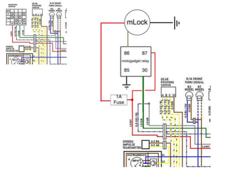
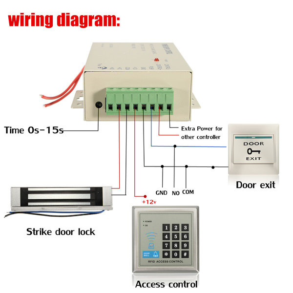
Collection of rfid access control wiring diagram. The rfid cards are useable from both sides of the module at max 5cm. This allows for easy use in. Assortment of rfid access control wiring diagram youll be able to download at no cost. It shows the components of the circuit as simplified forms and the power as well as signal links in between the gadgets. Block diagram of the system.
Assortment of rfid access control wiring diagram. A wiring diagram is a simplified standard pictorial representation of an electrical circuit. It reveals the parts of the circuit as simplified forms and the power and signal connections between the tools. Posted on may 25 2018.
Gallery of Rfid Wiring Diagram