Rotary encoders are of several types. I have a question on wiring a 4 wire rotary encoder.
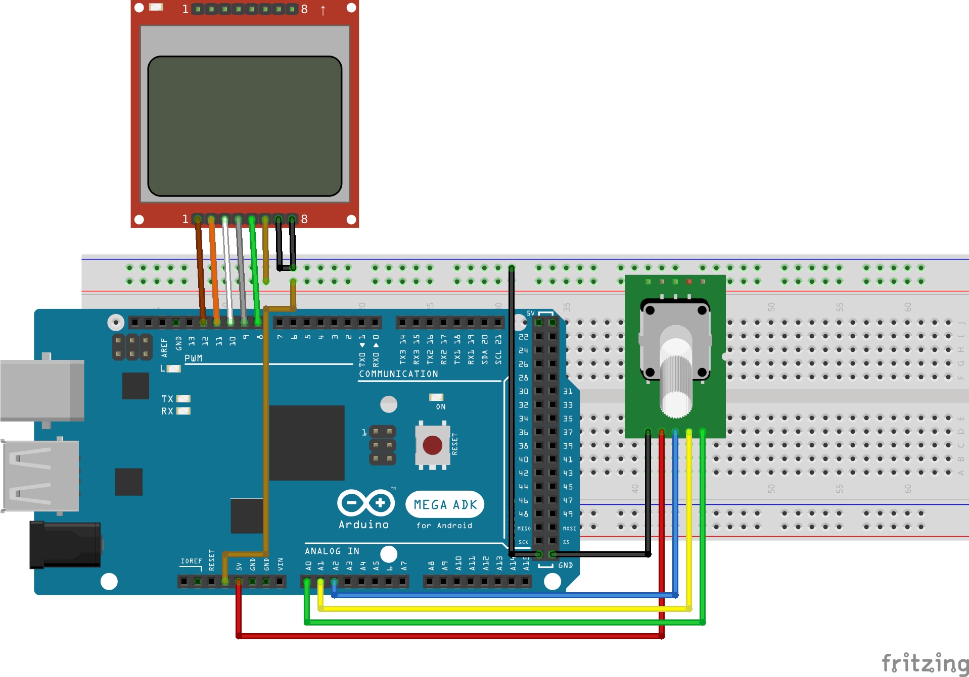
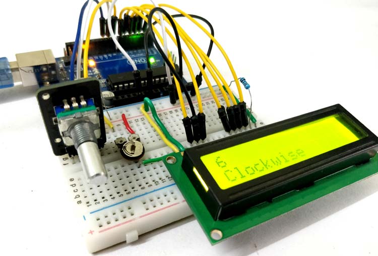
Rotary Encoder With Arduino And Nokia 5110 Lcd Tutorial
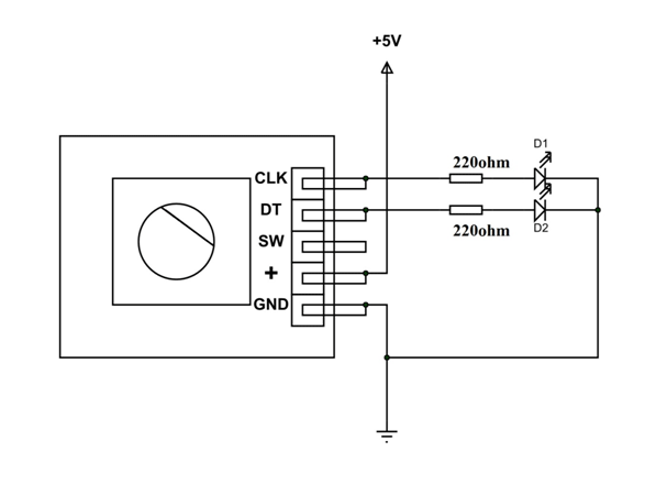
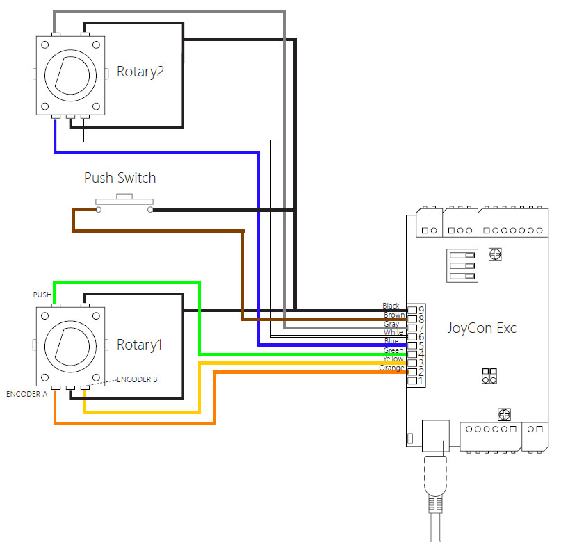
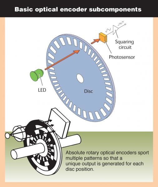
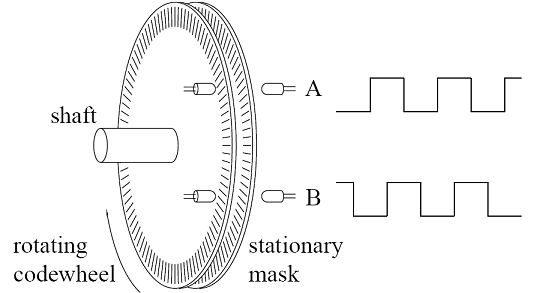
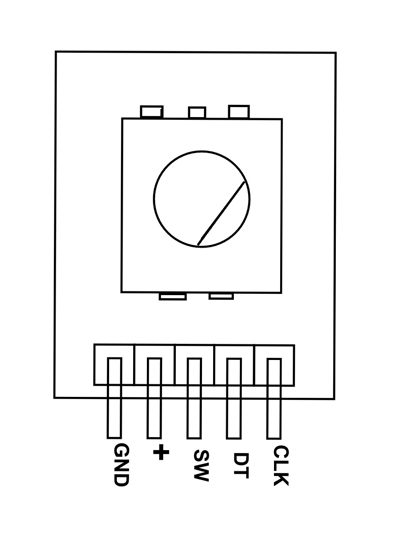
Rotary encoder wiring diagram. Encoder wiring schemes can be unique to each encoder and one should follow the diagram or pinout designated on the encoder datasheet. Introduction selection guide 4 measuring principles accuracy 14 mechanical design types and mounting rotary encoders with stator coupling 16 rotary encoders for separate shaft coupling 19 shaft couplings 24 general mechanical information 27 safety related position measuring systems 30 specifi cations absolute rotary encoders incremental rotary encoders. Quadrature encoders have dual channels a and b phased 90 electrical degrees apart. Incremental encoders are available in two basic output types single channel and quadrature. Lets connect rotary encoder to arduino. A single channel encoder often called a tachometer is normally used in systems that rotate in one direction only and require simple position and velocity information.
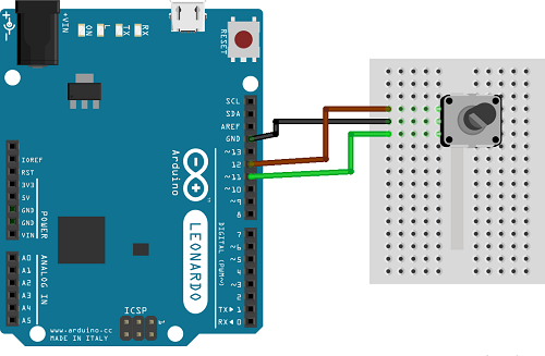
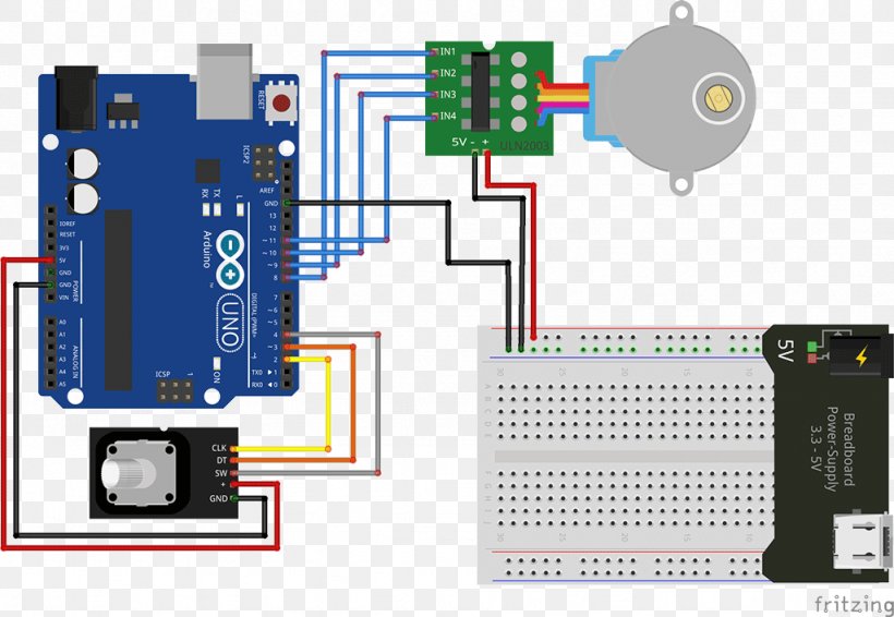
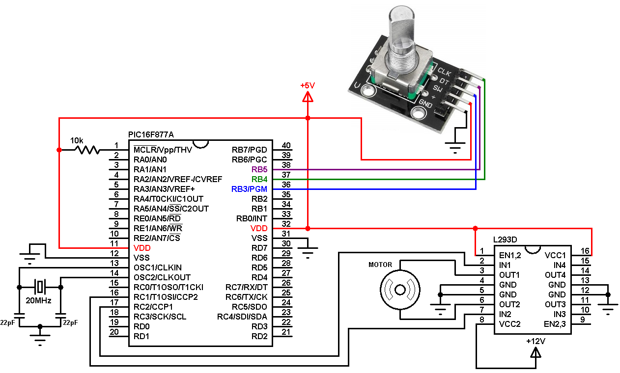
Start by connecting v pin on the module to 5v on the arduino and gnd pin to ground. I have searched diagrams for it and it seems like it is hooked up correctly. Wiring connecting rotary encoder to arduino. Connections are fairly simple. The output of absolute encoder is a value proportional to the current shaft angle while incremental encoders output is step of shaft and its direction. In this article we will see arduino rotary encoder wiring.
On most rotary encoders when you rotate them you will feel a bump known as steps and most rts have about 12 of these per rotation some have 24 or more. A rotary encoder rt is a device that you can rotate infinitely. I cannot find a lot of information about the output voltage. Basically this step is the minimum amount you can rotate the encoder to register any change. My input for can be between 5 24v i have attempted to probe the output voltage with a meter and get 1v. Now that we know everything about the rotary encoder it is time to put it to use.
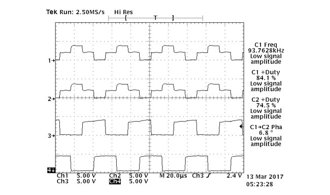
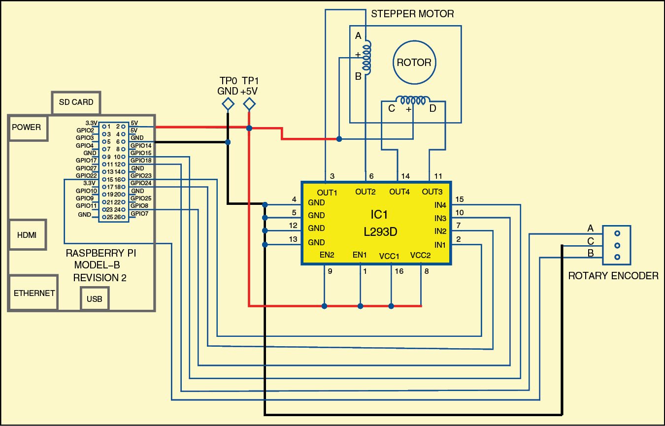
Multi channel differential encoder wiring with commutation tracks can have up to 14 wires and miswiring can result in signal issues such as deformed pulses low signal amplitude and shorted connections. Two main types include relative incremental and absolute encoders.
Gallery of Rotary Encoder Wiring Diagram