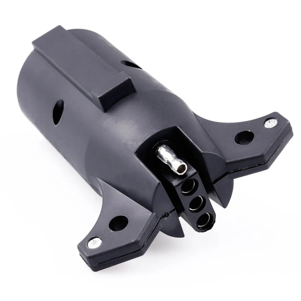
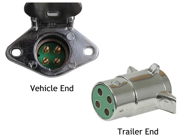
Note that this type of 4 pin connector is less common that 4 pin flat connector. 6 way systems round plug.

Wiring Diagram For A 7 Pin Flat Trailer Plug
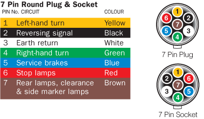
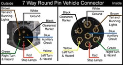
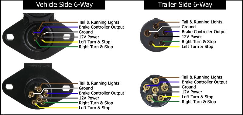
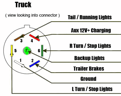
Round plug wiring diagram. Wiring diagrams for 7 way round trailer connectors. Round 1 14 diameter metal connector allows 1 or 2 additional wiring and lighting functions such as back up lights auxiliary 12v power or electric brakes. The most common variances on this diagram will be the bluebrake redacc wires will be inverted. The black sometimes red 12v and blue electric brakes wire may need to be reversed to suit the trailer. If there is no red or blue wire and there is both a black a white wire normally the black will be brakes and the white ground. Check with a test light or vom.
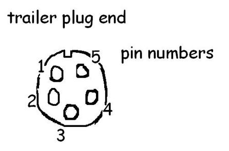
Top right red electric brake or 12 volt power. 4 pin trailer wiring diagram. If you are looking at the back of the trailer end plug to put in the wires the functions will be. Im looking at my 7 pin cast body pollak round pin receptacle vehicle side pin labels on the screw side of the terminals and they are labeled differently than in your color diagram. Bottom right green right turn. Variety of 7 pin round trailer wiring diagram.
This type of connector is normally found on utvs atvs and trailers that do not have their own braking system. 10222009 95014 am. This wiring scheme is for reference only. Always test wires for function and wire accordingly. 4 5 way flat connector wiring diagrams 4 way and 5 way flat connectors use color coded wires and are available in a variety of lengths. It reveals the parts of the circuit as simplified forms as well as the power and also signal links between the tools.
If your vehicle is not equipped with a working trailer wiring harness there are a number of different solutions to provide the perfect fit for your specific vehicle. Top left white ground. Wiring plug diagram created date. 6 way round trailer side 4 way round trailer side 5 way flat trailer side 7 way pin style car side wire color key 7 way rv blade style car side 6 way round car side 4 way round car side. Below is the generic schematic of how the wiring goes. A wiring diagram is a simplified standard pictorial depiction of an electric circuit.
Bottom left yellow left turn. Top brown taillights. Above we have describes the main types of trailer wiring diagrams. They can be purchased as a standalone plug for the truck or trailer or as a complete loop with both the plug and the socket included. 5 way round trailer plug wiring diagram wiring diagram is a simplified standard pictorial representation of an electrical circuitit shows the components of the circuit as simplified shapes and the aptitude and signal connections together with the devices. The male trailer side plug is correctly labeled but the body side connector has the yellow and green.
Complete with a color coded trailer wiring diagram for each plug type this guide walks through various trailer wiring installation solution including custom wiring splice in wiring and replacement wiring. Center blue red electric brake or 12 volt power.
Gallery of Round Plug Wiring Diagram