Figure 4 is a pin diagram for both 25 pin rs485 pinout half duplex and full duplex pinout connectors. Rs485 pin configuration for db 25.
What S The Difference Between The Rs 232 And Rs 485 Serial
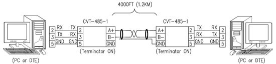
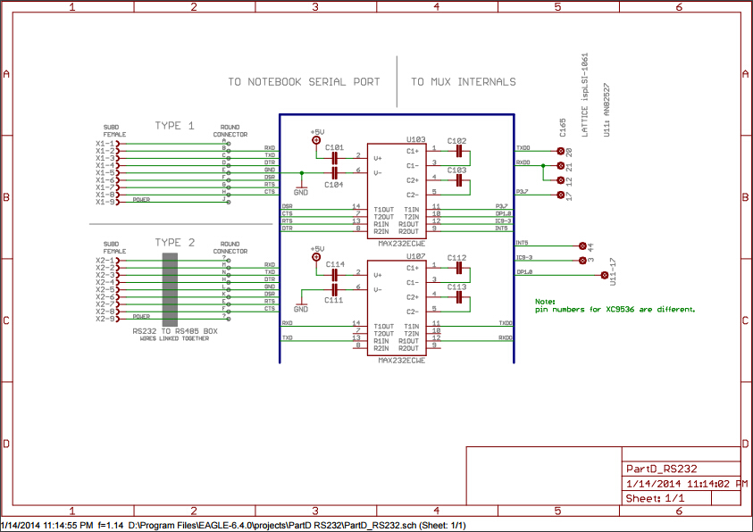
Rs232 to rs485 wiring diagram. The rs232 rs485 adapter circuit diagram is show below rs232 db9 is used as the rs232 port while only a terminal block is used as rs485 connector. To perform a loopback test with no hardware flow control with a db 25 connector connect pins 2 to 3 for rs 232. For rs 422485 connect pins 5 to 20 and 7 to 22. Pinout diagram for db 25 connector. 9 pin d sub female connector. Pinouts rs 232 and other serial ports and interfaces.
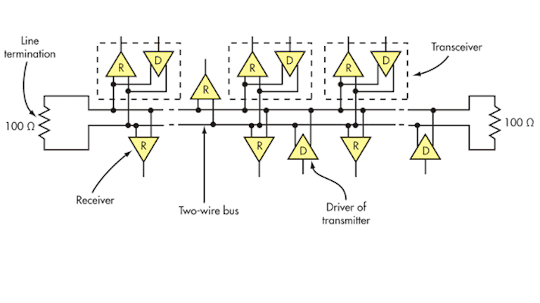
The rs232 rs485 adapter circuit diagram is show below rs232 db9 is used as the rs232 port while only a terminal block is used as rs485 connector. It reveals the parts of the circuit as simplified shapes and the power as well as signal links in between the gadgets. A twisted pair is ideal for rs485 cable since the twisting make both wires and exposed to an identical noise figure thus canceling the noise itself when received at the interface port. Pinouts devices connectors. The txd and txd lines carry transmit data while the rxd and rxd contain the receive data. Pinout of rs232 to rs485 cable and layout of 9 pin d sub female connectorelectrically isolated rs485 communication interface to the pc serial port.
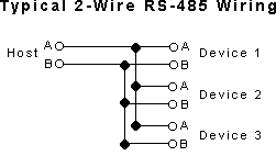
Serial interface pin assignment. A twisted pair is ideal for rs485 cable since the twisting make both wires and exposed to an identical noise figure thus canceling the noise itself when received at the interface port. Variety of rs485 wiring diagram. Most of the pins on db 25 connectors are not connected since only nine pins are used for rs 232 rs 422 and rs 485 communication. A wiring diagram is a streamlined traditional pictorial representation of an electric circuit. Rs232 to rs485 cable pinout.
Figure 3 is an rs485 wiring diagram for rs485 pinout db9 connectors.
Gallery of Rs232 To Rs485 Wiring Diagram