It shows the components of the circuit as simplified shapes and the knack and signal connections amongst the devices. Ensure the crossover between the interface and lexium mdrive rxtx txrx ensure the crossover between the interface and lexium mdrive rxtx txrx ground is galvanically isolated on the lexium.

Troubleshooting Communications To A Micrologic Trip Unit
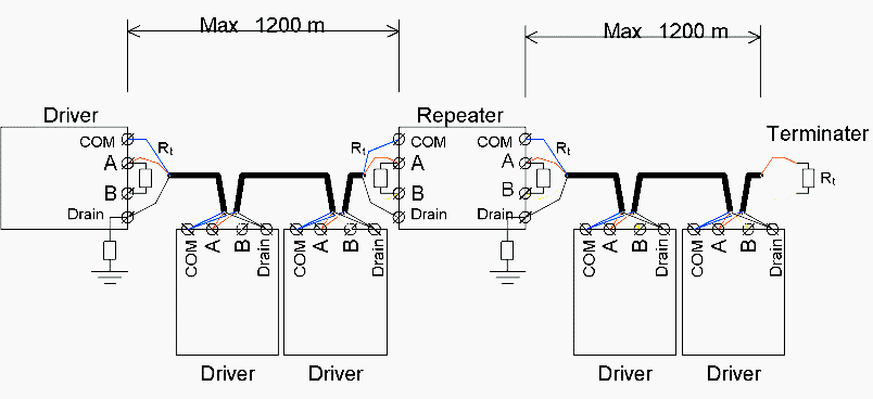
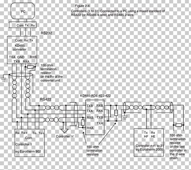
Rs485 4 wire wiring diagram. Rs 485 is designed to transmit this information over significant lengths and 1000 meters are well within its capability. Rs485 recommended wiring. Summary the rs 485 standard defines a multi point data communications interface using a balanced pair plus common called 2 wire however many. Rs485 4 wire wiring diagram wiring diagram is a simplified up to standard pictorial representation of an electrical circuit. The distance and the data rate with which rs 485 can be successfully used depend a great deal on the wiring of the system. For ni serial hardware connector pinout diagrams refer to the serial quick reference guide.
Sciences offers the cnv 100 rs 485 2 wire to 4 wire converter. Refer to set up 2 wire half duplex communication with rs 485 port for the pinouts and more details. In addition to the data wires it is worth considering whether to use a shielded cable braidfoil connected to signal earth. The following diagrams show the recommended schemas for 2 wire and 4 wire configurations for farsync cards such as the farsync flex and farsync t2ee. Half duplex 2 wire for 2 wire transmission you will need to short the transmit txd and receive rxd signals together on the rs 485 port. Full duplex 4 wire only.
Rs 485 is designed to be a balanced system. This device is pre engineered to allow interoperability of 2 wire and 4 wire rs 485 devices in a variety of configurations. Single lexium mdrive full duplex point to point configuration notes and checkpoints.
Gallery of Rs485 4 Wire Wiring Diagram