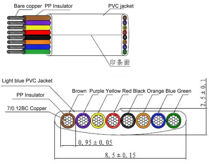
The distance and the data rate with which rs 485 can be successfully used depend a great deal on the wiring of the system. Pin 8 brown wire pin 8.

Cat6 Module Wiring Diagram
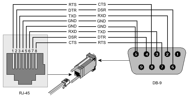
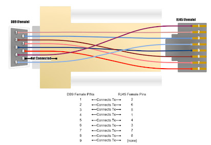
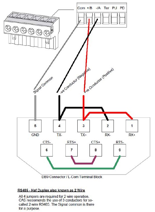
Rs485 to rj45 wiring diagram. 3 r remote off required or remote off control 4 tr data line required for rs485 communication. Figure 3 is an rs485 wiring diagram for rs485 pinout db9 connectors. Half duplex 2 wire for 2 wire transmission you will need to short the transmit txd and receive rxd signals together on the rs 485 port. Appendix a pin out of rj12 rj45 connectors rj12 connectors pin signal name description 1 not used 2 tr data line required for rs485 communication. Rs 485 is designed to be a balanced system. Faq how do i test my 2 wire rs 485 port or converter bbbest ethernet wiring diagram fresh 108 quality cable managementawesome rj45 to rj11 cable pinout the whole lot you want torj12 to rj45 wiring diagram rj9s8pinout female symbols wiresplc pc scada answers 2010resume forty four specific cat 5 wiring diagram excessive definition.
Cut off the rs 485 plug indicated above leaving about 3 inches of wire attached. Locate the rj45 cable that was shipped with your mt50 remote or if you are using a longer rj45 cable you will need that cable instead. Follow these steps to make sure you make the perfectly crimped rj45 connector. Rj45 cross over ethernet cable pinout how to crimp a rj45 ethernet cable. Click to find view print and more. The complete ethernet pinout cable wiring reference with wiring step by step guide.
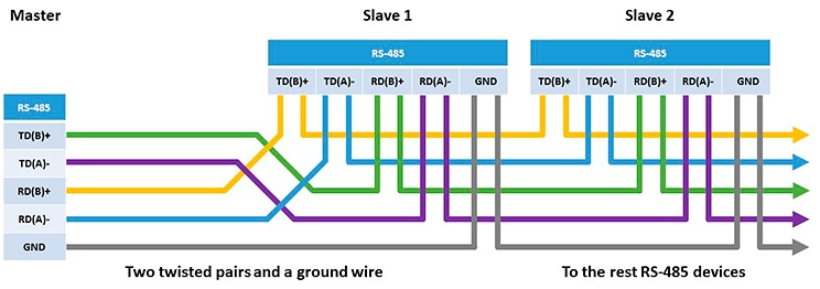
Rs 485 is designed to transmit this information over significant lengths and 1000 meters are well within its capability. The corresponding pins will depend on your devices user manual and the rs 485 cable connector type. Rj45 pinout diagram shows wiring for standard t568b t568a and crossover cable. 5 not used 6 rtn signal return common reference for logical signals. Figure 4 is a pin diagram for both 25 pin rs485 pinout half duplex and full duplex pinout connectors. Is to inform momentum processor and tesysu users how to wire an lulc031 to a 172jnn21032 option adapter via its port 2 rs485 rj45 connector for proper communications.
The distances these signals are carried is greater due to differential signals. Rs485 wiring diagram from a 172jnn21032 port 2 rj45 to an lulc031 modbus interface. Click to check the right one for you or print as reference. Cut off one of the rj45 plugs and strip the cable exposing the wires. For ni serial hardware connector pinout diagrams refer to the serial quick reference guide. Connect the wires from the rs 485 plug you obtained.
Remember the rj45 wiring order. Trim off any nylon strands or wire guides. Trim the outer sheath back about 10mm to expose the inner conductors. Rj45 connectors pin. The txd and txd lines carry transmit data while the rxd and rxd contain the receive data.
Gallery of Rs485 To Rj45 Wiring Diagram